
Fingerprint identification apparatus

a fingerprint identification and apparatus technology, applied in the field of optoelectronic apparatus, can solve the problems of affecting image capture quality, affecting the quality of fingerprint recognition, and affecting the quality of fingerprint recognition, and achieve the effect of good quality

Inactive Publication Date: 2018-11-15
GINGY TECH
View PDF2 Cites 3 Cited by
  • Summary
  • Abstract
  • Description
  • Claims
  • Application Information

AI Technical Summary

Benefits of technology

The invention is a fingerprint identification apparatus that can capture high-quality fingerprint images. It achieves this by using a transparent substrate with a rough surface or a light guide element with scattering particles. This prevents interference with the fingerprint information from reflected, light beams that may carry image information. As a result, the apparatus can capture clear fingerprint images, facilitating fingerprint recognition.

Problems solved by technology

When the light beam reflected by the fingerprint passes through the plurality of periodically-arranged optical microstructures, the light beam originally carrying a complete fingerprint image is damaged by the periodically-arranged optical microstructures.
As a result, image capture quality is affected, which is counterproductive to fingerprint recognition.

Method used


Image

  • Fingerprint identification apparatus
  • Fingerprint identification apparatus
  • Fingerprint identification apparatus

Examples


Embodiment Construction

[0024]Hereinafter, exemplary embodiments are described in detail, and examples of the exemplary embodiment are conveyed via the figures. Wherever possible, the same reference numerals are used in the drawings and the descriptions to refer to the same or similar portions.

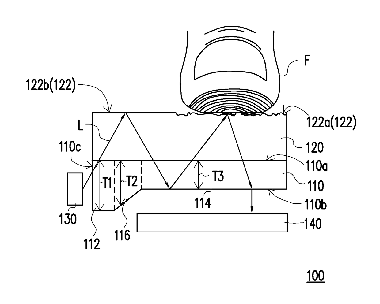
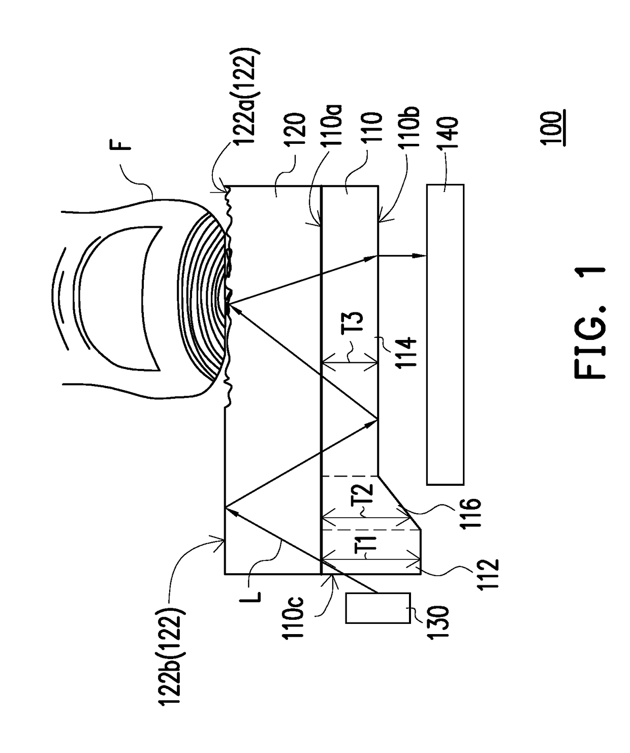
[0025]FIG. 1 is a cross section of a fingerprint identification apparatus of an embodiment of the invention. Referring to FIG. 1, a fingerprint identification apparatus 100 includes a light guide element 110, a transparent substrate 120, a light source 130, and an image-sensing element 140. The light guide element 110 has a first surface 110a, a second surface 110b opposite the first surface 110a, and a side 110c connected between the first surface 110a and the second surface 110b. For instance, in the present embodiment, the light guide element 110 can include a light-coupling portion 112 adjacent to the light source 130 and having a side 110c and a light guide portion 114 away from the light source 130, wherein a t...


PUM


Abstract

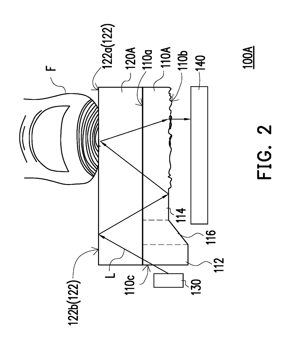
A fingerprint identification apparatus including a light guide element, a transparent substrate, a light source, and an image-sensing element is provided. The light guide element has a first surface, a second surface opposite the first surface, and a side connected between the first surface and the second surface. The transparent substrate is disposed on the first surface of the light guide element and has a pressing surface to be pressed by a finger. The light source is configured to emit a light beam and is disposed adjacent to the side of the light guide element. The image-sensing element is disposed opposite to the second surface of the light guide element. The pressing surface of the transparent substrate or the second surface of the light guide element is an irregular rough surface.

Description

CROSS-REFERENCE TO RELATED APPLICATION[0001]This application is a continuation-in-part application of and claims the priority benefit of U.S. application Ser. No. 14 / 822,891, filed on Aug. 10, 2015, now pending, which claims the priority benefits of U.S. provisional application Ser. No. 62 / 067,966, filed on Oct. 23, 2014. This application also claims the priority benefits of U.S. application Ser. No. 62 / 563,045, filed on Sep. 25, 2017, U.S. application Ser. No. 62 / 574,222, filed on Oct. 19, 2017, and China application serial no. 201820172153.8, filed on Feb. 1, 2018. The entirety of each of the above-mentioned patent applications is hereby incorporated by reference herein and made a part of this specification.BACKGROUND OF THE INVENTIONField of the Invention[0002]The invention relates to an optoelectronic apparatus, and more particularly, to a fingerprint identification apparatus.Description of Related Art[0003]Fingerprint recognition is the mainstream technique of current biometric...

Claims


Application Information

Patent Timeline
Patent Type & Authority Applications(United States)
IPC IPC(8): G06K9/00G02B6/42
CPCG06K9/0004G02B6/4298G02B6/0028G02B6/0043G06V40/1324G06V40/1318
Inventor LIN, PATRICKWU, JEN-CHIEH
Owner GINGY TECH
Learn More