Infrared microscope
- Summary
- Abstract
- Description
- Claims
- Application Information
AI Technical Summary
Benefits of technology
Problems solved by technology
Method used
Image
Examples
first embodiment
The First Embodiment
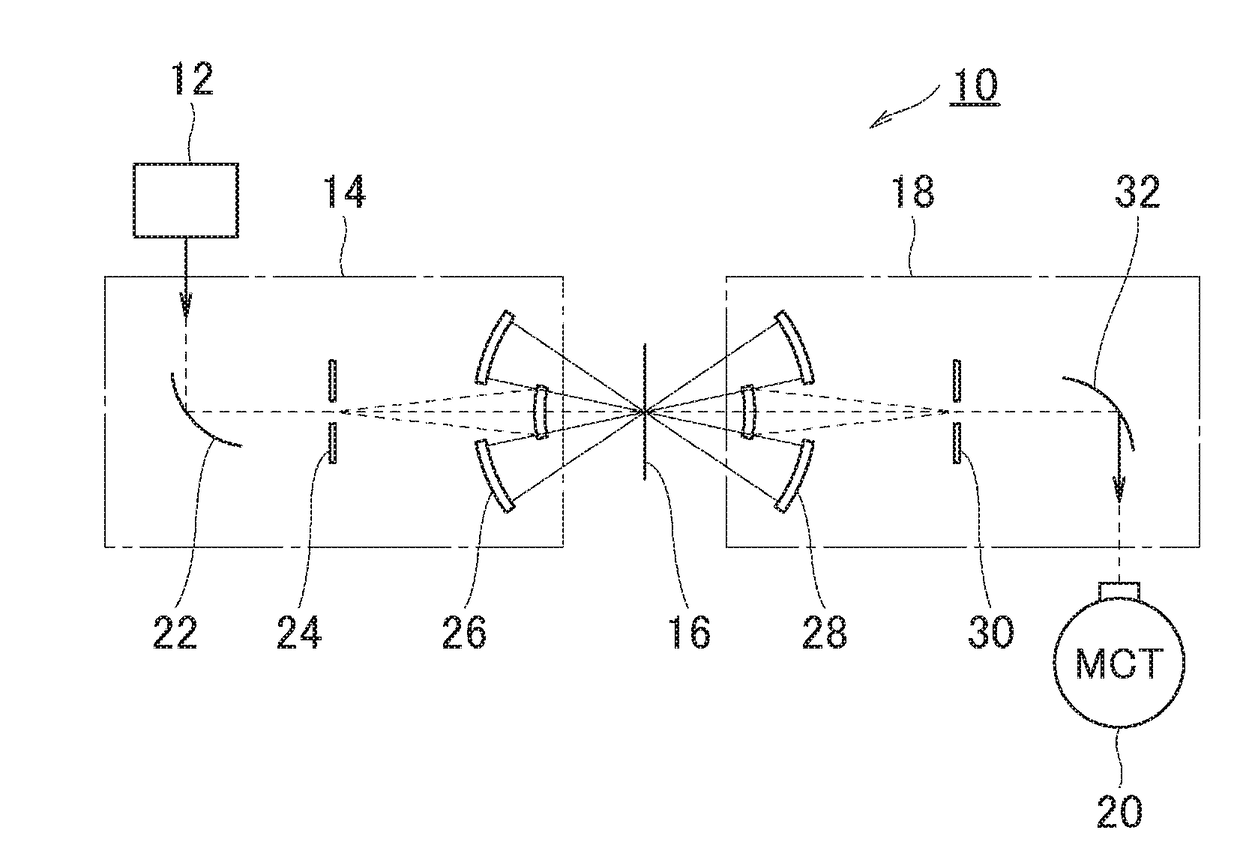
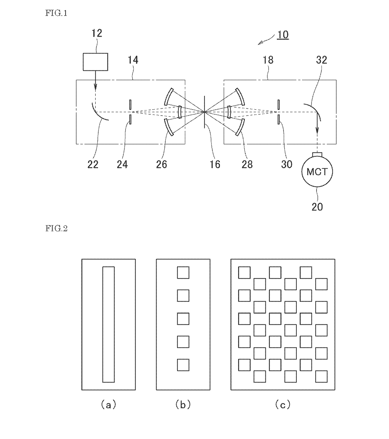
[0036]FIG. 1 is a schematic diagram of the infrared microscope according to the first embodiment of the present invention. It is a simplified schematic configuration, so that explanation of the present embodiment becomes easier. Therefore, although it is not shown in FIG. 1, configuration components which are necessary for general microscopes such as a movable stage for placing the sample, a computer for analyzing, the detection light, and the like are comprised. The infrared microscope 10 shown in FIG. 1 comprises a light source 12 for irradiating an infrared light, an infrared light irradiating optical system 14 for irradiating the emitted infrared light to a sample 16, an infrared light focusing optical system 18 for focusing the infrared light transmitted through the sample 16, and a MCI detector 20 for detecting the focused infrared light.
[0037]Characteristic features of the present invention are that the infrared light irradiating optical system 14 comprise...
second embodiment
The Second Embodiment
[0051]Next, an infrared microscope according to the second embodiment of the present invention is described in detail with reference to figures. Configurations in common with the infrared microscope 10 of the first embodiment shown in FIG. 1 are represented with reference numbers of which 100 are added respectively.
[0052]FIG. 5 is a schematic diagram of the infrared microscope according to the second embodiment of the present invention. The infrared microscope 110 shown in FIG. 5 comprises a light source 112 for irradiating an infrared light, an infrared light irradiating optical system 114 for irradiating the emitted infrared light to a sample 116, an infrared light focusing optical system 118 for focusing the infrared light transmitted through or reflected by the sample 116, and a MCT detector 120 for detecting the focused infrared light.
[0053]The present embodiment is an embodiment which uses the present invention to a Fourier transform infrared spectrometer ...
third embodiment
[0064]Next, an infrared microscope according to a third embodiment of the present invention is described with reference to the figures. Configurations in common with the infrared microscope 110 of the second embodiment shown in FIG. 5 are represented with reference numbers of which 100 are added respectively.
[0065]FIG. 6 is a schematic diagram of the infrared microscope according to the third embodiment of the present invention. The infrared microscope 210 shown in FIG. 6 comprises: a light source 212 for emitting an infrared light; an infrared light irradiating optical system 214 for irradiating the emitted infrared light to a sample 216; an infrared light focusing optical system 218 for focusing the infrared light transmitted through or reflected by the sample 216; and a MCT detector 220 for detecting the focused infrared light. The present embodiment is also an embodiment that uses the present invention to a similar FTIR like the second embodiment.
[0066]A characteristic feature o...
PUM
 Abstract
Description
Claims
Application Information
 - R&D
- Intellectual Property
- Life Sciences
- Materials
- Tech Scout
- Unparalleled Data Quality
- Higher Quality Content
- 60% Fewer Hallucinations
Browse by: Latest US Patents, China's latest patents, Technical Efficacy Thesaurus, Application Domain, Technology Topic, Popular Technical Reports.
© 2025 PatSnap. All rights reserved.Legal|Privacy policy|Modern Slavery Act Transparency Statement|Sitemap|About US| Contact US: help@patsnap.com


