Dual conversion gain high dynamic range readout for comparator of double ramp analog to digital converter

Active Publication Date: 2018-10-18
OMNIVISION TECH INC
View PDF0 Cites 21 Cited by
  • Summary
  • Abstract
  • Description
  • Claims
  • Application Information

AI Technical Summary

Benefits of technology

The patent text describes a new technique for image sensors that allows for high dynamic range (HDR) photography. This is achieved by using a pixel array with dual conversion gain (DCG) operation. The DCG operation involves reading from pixels under low and high gain modes, and combining the two readouts to obtain HDR. However, there can be a difference in reset level between the pixels in the high and low conversion gain modes. The patent text describes various techniques to address this issue, such as using two comparators or compensating for parasitic capacitances. The technical effect of the patent text is to provide a more effective solution for reducing the effects of parasitic capacitances on frame rate and to improve the accuracy and reliability of HDR photography.

Problems solved by technology

However, there may be a large difference in a reset level of the pixels in high and low conversion gain modes.
Many techniques have been employed to mitigate these effects, but some of these methods may not entirely eliminate the effects.

Method used


Image

  • Dual conversion gain high dynamic range readout for comparator of double ramp analog to digital converter
  • Dual conversion gain high dynamic range readout for comparator of double ramp analog to digital converter
  • Dual conversion gain high dynamic range readout for comparator of double ramp analog to digital converter

Examples


Embodiment Construction

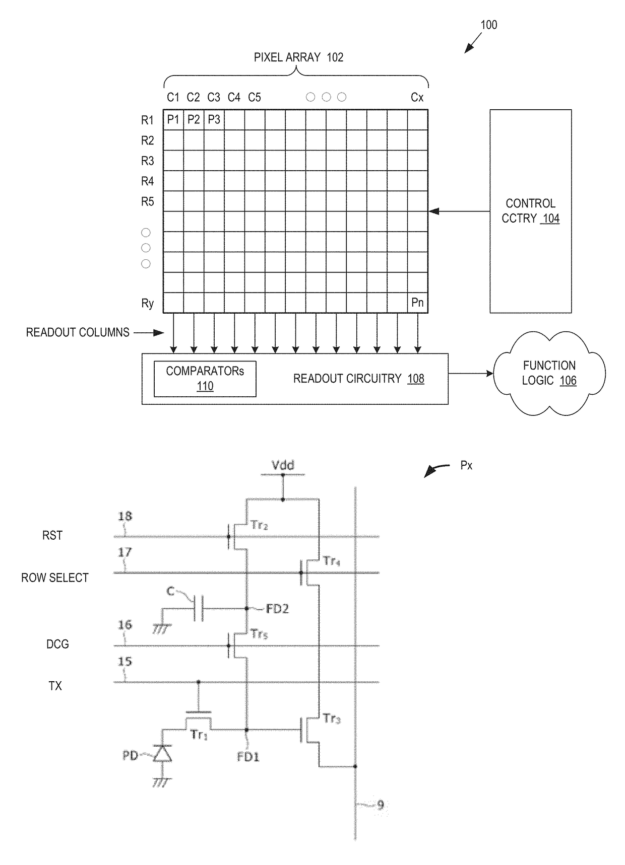
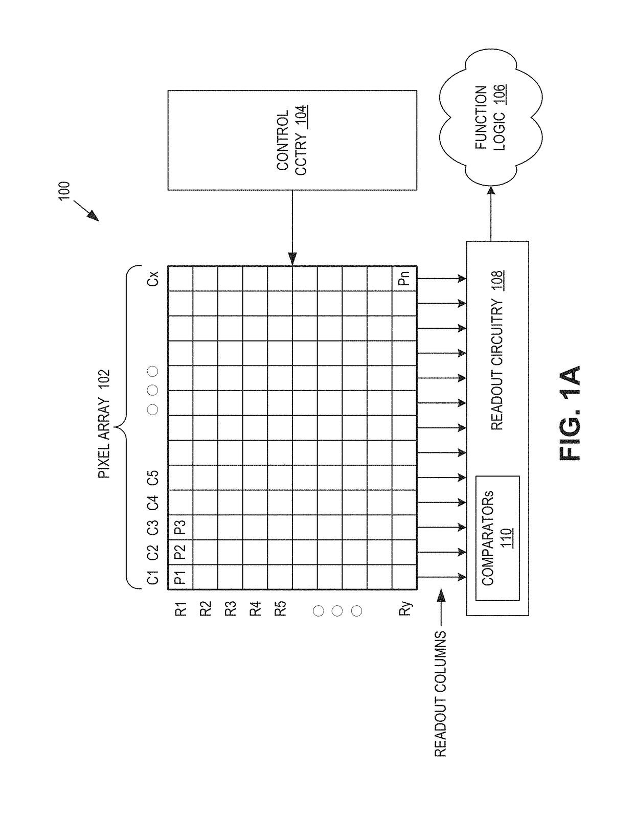
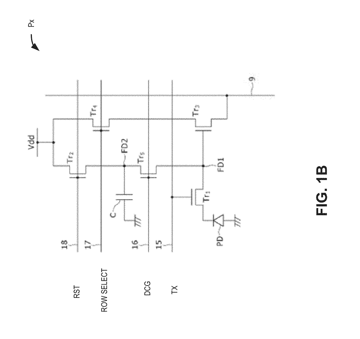
[0011]Examples of an apparatus and method for an image sensor with a two-input dual stage comparator for dual conversion gain high dynamic range operation are described herein. In the following description, numerous specific details are set forth to provide a thorough understanding of the examples. One skilled in the relevant art will recognize; however, that the techniques described herein can be practiced without one or more of the specific details, or with other methods, components, materials, etc. In other instances, well-known structures, materials, or operations are not shown or described in detail to avoid obscuring certain aspects.

[0012]Reference throughout this specification to “one example” or “one embodiment” means that a particular feature, structure, or characteristic described in connection with the example is included in at least one example of the present invention. Thus, the appearances of the phrases “in one example” or “in one embodiment” in various places through...


PUM


Abstract

Example comparators as discussed herein may include a second stage coupled to provide an output in response to an intermediate voltage, a first stage coupled to provide the intermediate voltage in response to an input. The first stage including a pair of cascode devices coupled to a current mirror, a low gain input coupled to inputs of the first stage via first switches, and further selectively coupled to the pair of cascode devices via second switches, and a high gain input coupled to the first and second inputs of the first stage via the first switches, and further selectively coupled to the pair of cascode devices via fourth switches. Based on a low conversion gain mode, the low gain input may be coupled to the inputs by the first switches, and further coupled to the pair of cascode devices by the second switches in response to a control signal being in a first state, and based on a high conversion gain mode, the high gain input may be coupled to the first and second inputs by the first switches, and further coupled to the pair of cascode device by the fourth switch in response to the control signal being in a second state.

Description

TECHNICAL FIELD[0001]This disclosure relates generally to image sensors, and in particular but not exclusively, relates to dual conversion gain for high dynamic range image sensors.BACKGROUND INFORMATION[0002]Image sensors have become ubiquitous. They are widely used in digital still cameras, cellular phones, security cameras, as well as, medical, automobile, and other applications. The technology used to manufacture image sensors has continued to advance at a great pace. For example, the demands of higher resolution and lower power consumption have encouraged the further miniaturization and integration of these devices.[0003]Image sensors may implement dual conversion gain to obtain high dynamic range. The high dynamic range may be obtained by reading from pixels under low gain, then high gain, and then combining the two readouts. However, there may be a large difference in a reset level of the pixels in high and low conversion gain modes. While the difference in reset level may be...

Claims


Application Information

Patent Timeline
IPC IPC(8): H04N5/355H04N5/3745H04N5/378H04N5/243H01L27/12
CPCH04N5/355H04N5/37455H01L27/1255H04N5/243H04N5/378H04N25/77H04N25/78H04N25/771H04N25/75
Inventor EBIHARA, HIROAKI
Owner OMNIVISION TECH INC
Why Eureka
Try Eureka