
Anisotropic Electrically Conductive Film and Connection Structure

an electrically conductive film and anisotropic technology, applied in the direction of film/foil adhesives without carriers, film/foil adhesives, conductors, etc., can solve problems such as connection resistance, and achieve the effects of reducing the effective mounting area, reducing the variation in the number of electrically conductive particles present within the rectangle, and reducing the number of electrically conductive particles

Active Publication Date: 2018-10-18
DEXERIALS CORP
View PDF2 Cites 8 Cited by
  • Summary
  • Abstract
  • Description
  • Claims
  • Application Information

AI Technical Summary

Benefits of technology

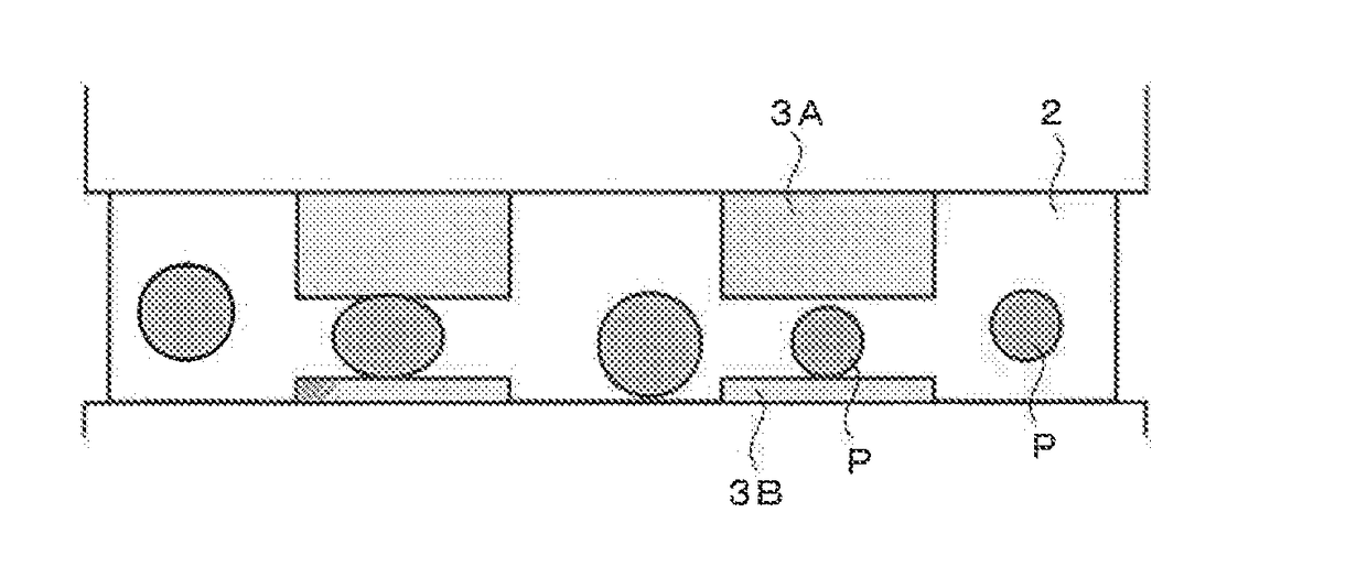
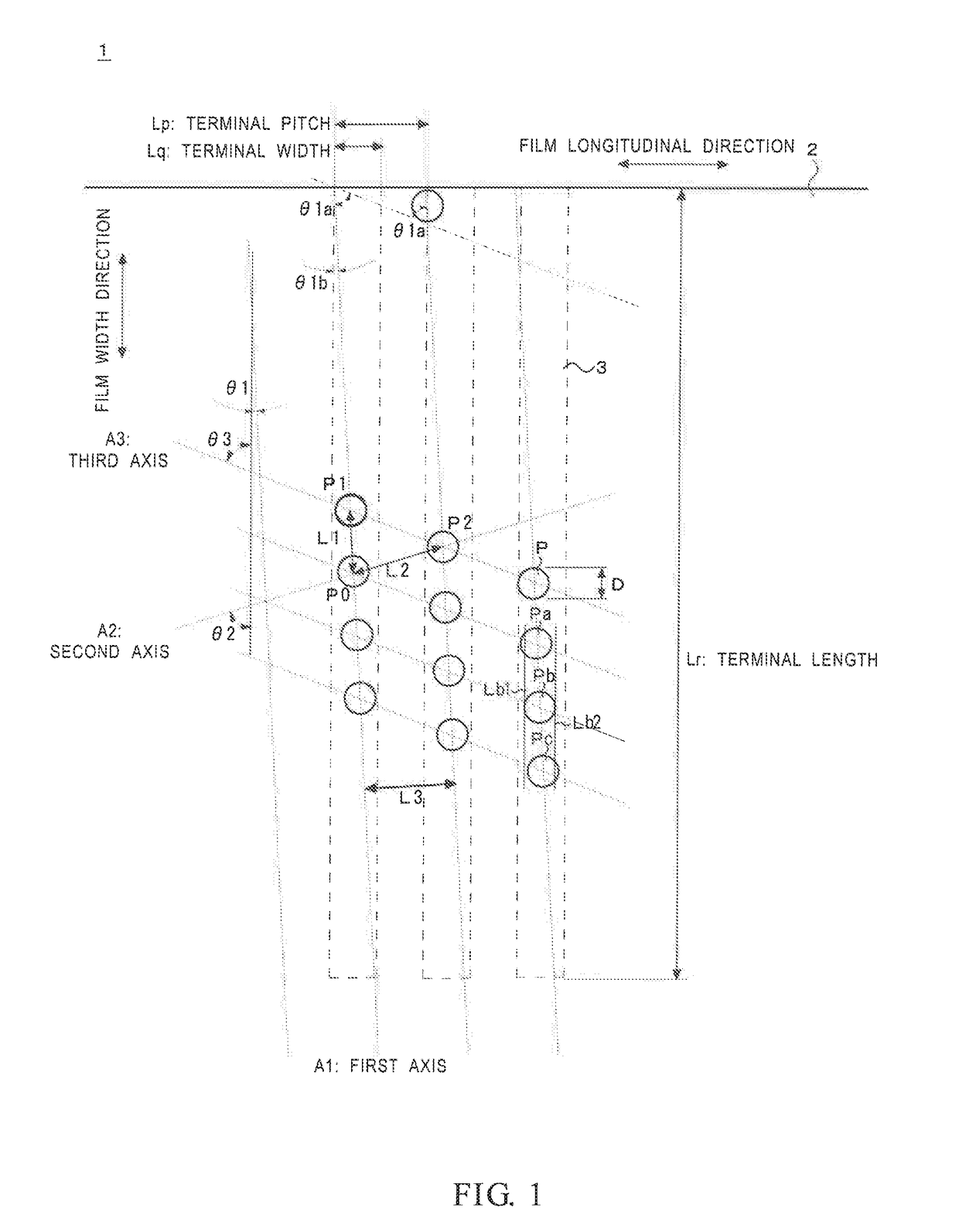
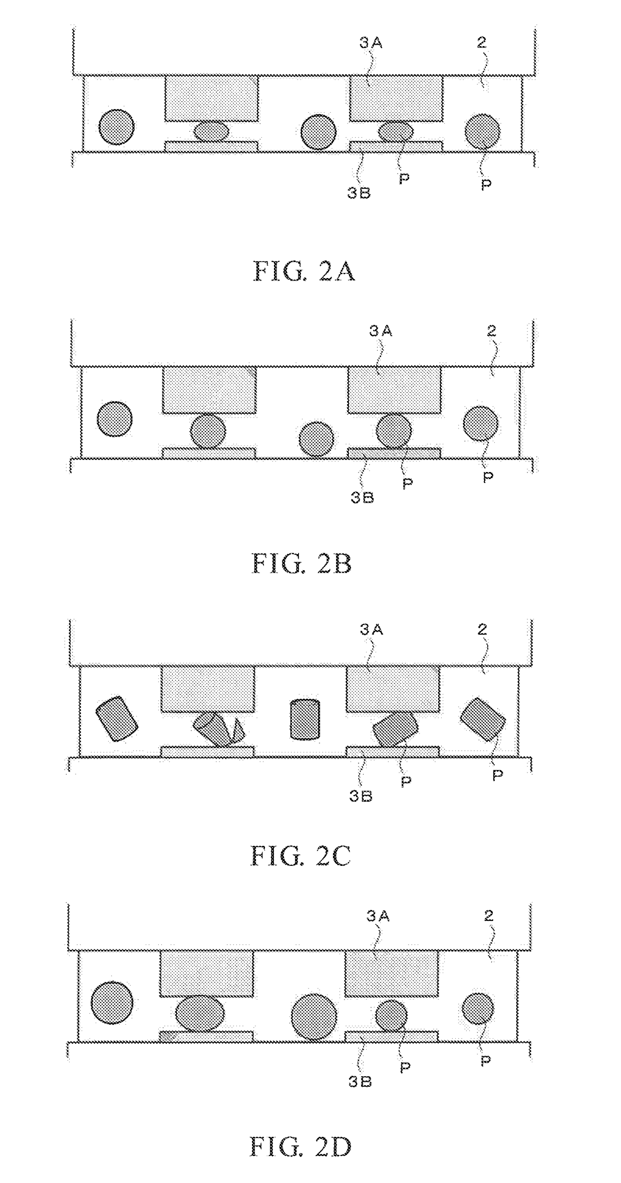
The present invention provides an anisotropic electrically conductive film that is suitable for improving conduction reliability and reducing production costs. The film includes electrically conductive particles arranged in a regular pattern, which ensures that even if a misalignment occurs between terminals, sufficient capturing of the particles is achieved. The film also has reduced variations in the number of particles present within a terminal, which makes the number of particles captured by the terminals stable. The film is compatible with terminals having a rectangular shape and arranged side by side at a certain spacing in a certain direction. The spacing between the terminals is adjusted so as to ensure a minimum interparticle spacing necessary for reliable conduction without excessively increasing the number density. The electrically conductive particles are substantially spherical, allowing for accurate checking of the connection status by the states of indentations or compression formed by the particles on the terminals. The film is also suitable for improving conduction reliability and reducing production costs associated with an increase in the density of the electrically conductive particles.

Problems solved by technology

However, there is a problem in that variations in connection resistance occur even though the electrically conductive particles are evenly disposed.

Method used


Image

  • Anisotropic Electrically Conductive Film and Connection Structure
  • Anisotropic Electrically Conductive Film and Connection Structure
  • Anisotropic Electrically Conductive Film and Connection Structure

Examples


examples 2 to 7

, Comparative Examples 2 to 5

[0158]To investigate the influence of the arrangements of the electrically conductive particles on the conduction characteristics, anisotropic electrically conductive films for COG of Examples 2 to 7 and Comparative Examples 2 to 5 were produced in the same manner as in Example 1 except that the arrangements of the electrically conductive particles were varied as shown in Table 2. The arrangement patterns of electrically conductive particles of the examples and the comparative examples were as illustrated in the drawings.

[0159]Connected objects for evaluation were produced using the obtained anisotropic electrically conductive films, and evaluations of the films were made in the same manner as in Example 1 for (a) initial conduction resistance, (b) indentation, and (c) particle capturing capability. In addition, (d) conduction reliability and (e) short-circuit occurrence rate were evaluated in the following manner.

[0160]These results, together with the r...

examples 8 to 10

[0168]To investigate the influence of the arrangements of the electrically conductive particles on the conduction characteristics, anisotropic electrically conductive films for FOG of Examples 8 to 10 were produced in the same manner as in Example 1 except that the arrangements of the electrically conductive particles were varied as shown in Table 3.

[0169]In this case, the connected objects for evaluation used were the following evaluation flexible printed circuit substrate and glass substrate, which were connected together with an effective mounting area of 100% or 80% (180° C., 80 MPa, 5 seconds).

[0170]Herein, the connected objects for evaluation having an effective mounting area of 100% refers to objects having no misalignment between the flexible printed circuit substrate and the glass substrate or having a misalignment range of not greater than 2%, and those of 80% refers to objects having a misalignment range of 20%.

[0171]Flexible printed circuit substrate for evaluation (FPC)...


PUM

PropertyMeasurementUnit
lengthaaaaaaaaaa
lengthaaaaaaaaaa
lengthaaaaaaaaaa

Abstract

An anisotropic electrically conductive film includes electrically conductive particles disposed in an electrically insulating adhesive layer. The particles are arranged at a predetermined pitch along first axes, arranged side by side, and are substantially spherical. The particle pitch at the first axes and the axis pitch of the first axes are both greater than or equal to 1.5D, D being an average particle diameter of the particles. Directions of all sides of a triangle formed by a particle (P0), which is one of the electrically conductive particles at one of the first axes, an electrically conductive particle (P1), which is at the one of the first axes and adjacent to the particle (P0), and an electrically conductive particle (P2), which is at another one of the first axes that is adjacent to the one of the first axes, are oblique to a film width direction of the conductive film.

Description

TECHNICAL FIELD[0001]The present invention relates to an anisotropic electrically conductive film and a connection structure connected via the anisotropic electrically conductive film.BACKGROUND ART[0002]Anisotropic electrically conductive films are widely used when mounting electronic components such as IC chips on substrates. In recent years, demand has risen for increasingly high wiring density in small electronic devices such as mobile phones and notebook-size personal computers. One well-known technology for achieving this high wiring density involves utilizing an anisotropic electrically conductive film in which electrically conductive particles are uniformly disposed in a lattice form in an electrically insulating adhesive layer of the anisotropic electrically conductive film.[0003]However, there is a problem in that variations in connection resistance occur even though the electrically conductive particles are evenly disposed. This is because, when the electrically insulatin...

Claims


Application Information

Patent Timeline
Patent Type & Authority Applications(United States)
IPC IPC(8): H01L23/00
CPCH01L24/29H01L24/32H01L24/27H01L2224/32225H01L2224/32145H01L2224/2939H01L2224/29455H01L2224/29457H01L2224/29439H01L2224/29447H01L2224/29444H01L2224/29464H01L2224/29387H01L2224/27464H01B5/16H01B13/0026H01L24/83C09J9/02C09J7/30C09J7/10C09J163/00C08K2003/0862C08L71/12C08L25/14C08K3/08H01L2224/271H01L2224/29357H01L2224/2712H01L2224/2929H01L2224/29339H01L2224/29344H01L2224/29347H01L2224/29355H01L2224/29364H01L2224/29499H01L2224/83851H01L2224/9211H01L2224/81903H05K3/323H05K2201/09945H01L2224/81H01L2224/83H01R11/01
Inventor SHINOHARA, SEIICHIRO
Owner DEXERIALS CORP
Learn More