
Reflective polarizing module for enabling bending reduction and back light unit having same

Active Publication Date: 2018-10-11
LMS
View PDF0 Cites 2 Cited by
  • Summary
  • Abstract
  • Description
  • Claims
  • Application Information

AI Technical Summary

Benefits of technology

[0027]The present invention for overcoming the aforementioned problems has the following advantageous effects.
[0028]According to an aspect of the present invention, in order to reduce bending caused by the increase in temperature of the reflective polarization sheet, by using a contraction ratio difference generated during the formation of the reflective polarization sheet, the bonding layer can be bonded to the reflect

Problems solved by technology

However, the reflective polarization sheet may be bent due to an increase in temperature, caused by elongated usage of the backlight unit.
However, when the reflective polarization sheet is used in a general LCD, heat is generated in the general LCD.
Thus, light transferr

Method used


Image

  • Reflective polarizing module for enabling bending reduction and back light unit having same
  • Reflective polarizing module for enabling bending reduction and back light unit having same
  • Reflective polarizing module for enabling bending reduction and back light unit having same

Examples


Example

BEST MODE

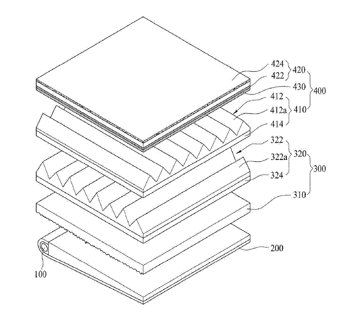
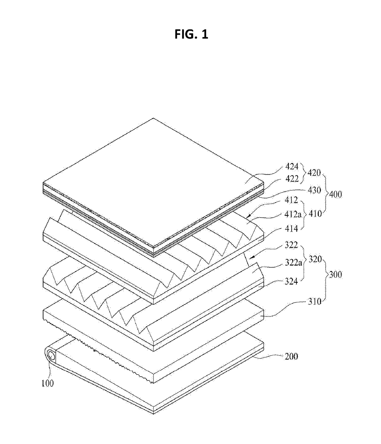
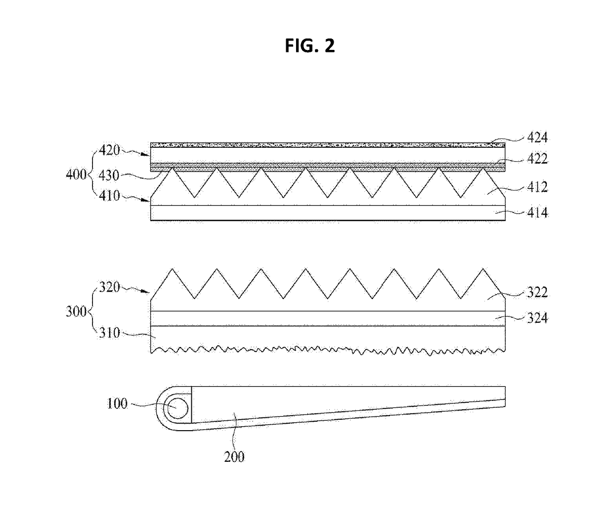
[0040]Hereinafter, exemplary embodiments of the present invention by which an object of the present invention can be concretely realized will be described with reference to the accompanying drawings. In describing the present embodiment, the same configurations are described using the same names and with the same reference numerals, and the excessive descriptions thereof will be omitted.

[0041]Hereinafter, it is illustrated that a backlight unit including a reflective polarizing module according to an embodiment of the present invention is applied to a flat liquid crystal display device, such as an LCD or LED panel. However, the present invention is not limited thereto, and an optical sheet may be independently used. The backlight unit may be applied to other apparatus rather than a liquid crystal display device, or may be applied to any device as long as a device such as a lighting device changes characteristics and a path of light.

[0042]

[0043]First, a schematic configurati...


PUM


Abstract

The present invention provides a reflective polarizing module for enabling bending reduction, comprising: a reflective polarizing sheet having a cooling surface in which a plurality of stacks having different refractive indices from each other are laminated to selectively transmit light and which is cooled by being in contact with a separate cooling roll in a heated state, and an outer exposed surface which is placed in a stacked form on an upper portion of the cooling surface and is exposed to air to thereby slowly cool, wherein the reflective polarizing sheet has a shrinkage rate of the cooling surface by means of a temperature rise which is relatively higher than the shrinkage rate of the outer exposed surface; and an adhesive layer which is provided to at least any one of the cooling surface or the outer exposed layer to thereby bond a separate optical module and the reflective polarizing sheet, and reduce shrinkage and bending of the reflective polarizing sheet according to a temperature rise due to a shrinkage rate difference between the cooling surface and the outer exposed surface.

Description

TECHNICAL FIELD[0001]The present invention relates to a reflective polarizing module enabling a reduction in bending and a backlight unit including the same, and more particularly, to a light concentrating module enabling a reduction in bending, capable of preventing bending of a reflective polarizing sheet by using a contraction ratio difference generated during the formation of the reflective polarizing sheet transmitting only specific polarized light, and a backlight unit including the same.BACKGROUND ART[0002]Recently, the use of flat display panels has increased, a liquid crystal display (LCD) being a representative flat display panel.[0003]Generally, unlike an existing cathode ray tube (CRT), such an LCD requires a backlight module providing light uniformly to an entire screen.[0004]Specifically, such a backlight unit has a configuration by which light is uniformly provided to a rear surface of the LCD, and is configured such that a light source, i.e. a light-emitting diode (L...

Claims


Application Information

Patent Timeline
IPC IPC(8): F21V8/00
CPCG02B6/0085G02B6/0055G02B6/0051G02B6/0056G02B6/0053G02F1/133528G02B6/0046G02F1/133606G02B6/0065G02F1/1335
Inventor LEE, EUN MICHO, JANG HEE
Owner LMS
Learn More