Thermoelectric power generation device
- Summary
- Abstract
- Description
- Claims
- Application Information
AI Technical Summary
Benefits of technology
Problems solved by technology
Method used
Image

Examples
first embodiment
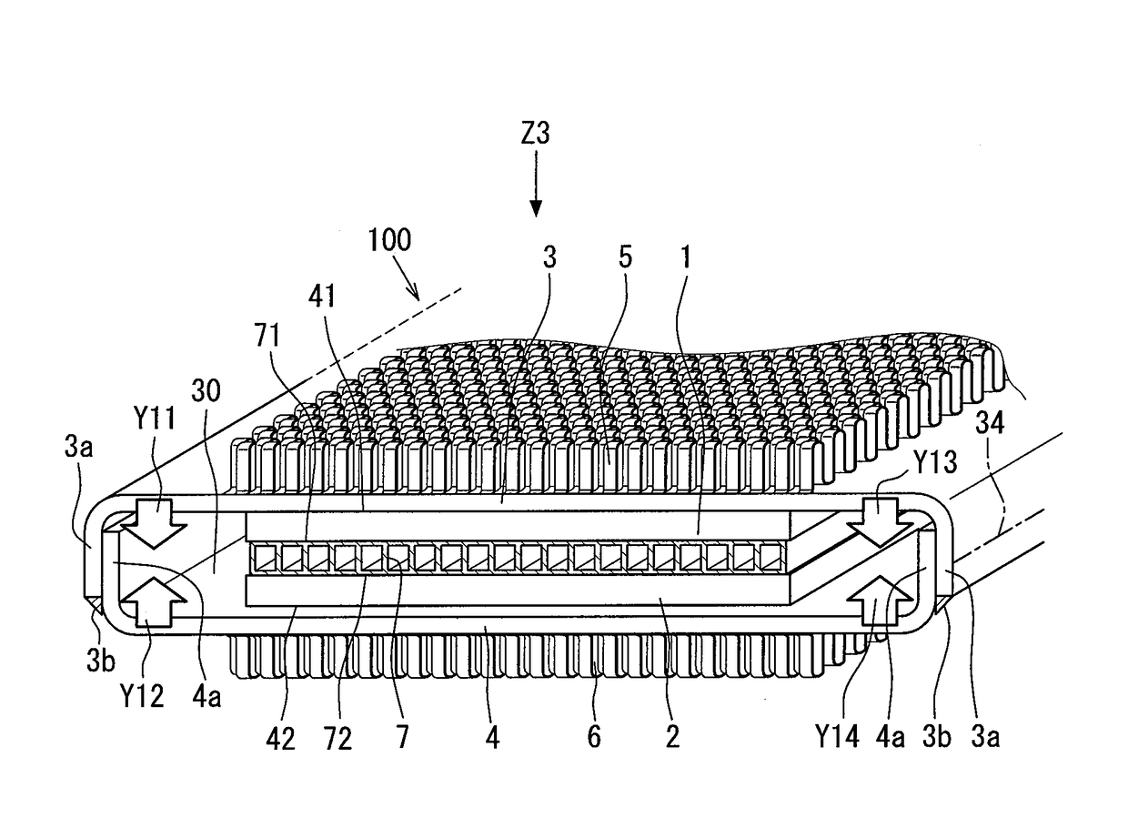
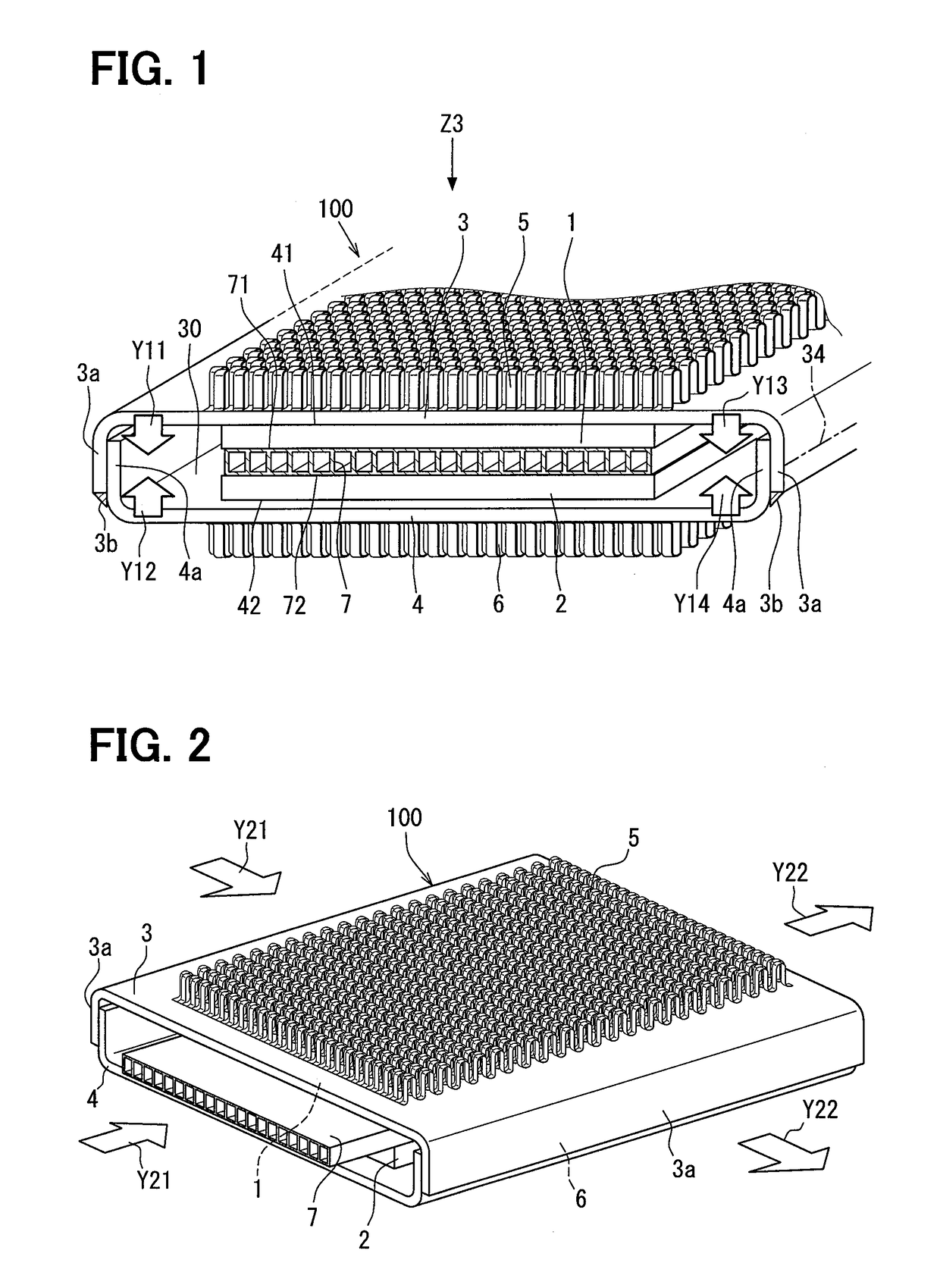
[0022]Hereinafter, a first embodiment will be described in detail by the use of FIG. 1 to FIG. 6. FIG. 1 is a construction view, partially in a cross section, of a thermoelectric power generation device 100. Power generation modules 1, 2 are received in an airtight case formed in a shape of a flat box so as to prevent elements from being oxidized. Hence, each of the power generation modules 1, 2 can be seen only as a box shaped like a plate when viewed from the outside, but many p-type semiconductor elements and n-type semiconductor elements are alternately connected to each other like a net in the airtight case constructed of a thin stainless steel plate. When the power generation module has one surface brought into contact with a high temperature part and has the other surface brought into contact with a low temperature part, the power generation module generates electric power. When the power generation modules 1, 2 are discriminated from each other, they are also referred to as ...
second embodiment
[0040]Next, a second embodiment will be described. Here, in the second embodiment, the same reference signs as in the first embodiment denote the same constructions as in the first embodiment and the preceding descriptions will be used therefor.
[0041]FIG. 7 shows a construction, in a front view, of a thermoelectric power generation device to show a second embodiment. As shown in FIG. 7, in the second embodiment, a size in an up and down direction of the duct 7 arranged in a central portion is made large to thereby easily apply a pressing force based on a thermal expansion to the first power generation module 1 and the second power generation module 2, which are arranged above and below the duct 7, by the thermal expansion. Here, an aspect ratio is a ratio of a long side to a short side in a rectangle. As shown in FIG. 7, an interior of the duct 7 is divided into a plurality of divided passages 7a and a sectional shape of each divided passage 7a is a rectangle. An engine cooling wate...
third embodiment
[0045]Next, a third embodiment will be described. Portions different from those in the above embodiments will be described. In FIG. 8, the first power generation module 1 and the second power generation module 2 are arranged in contact with the first outside plate 3 and the second outside plate 4 between the first outside plate 3 and the second outside plate 4. Then, the duct 7 is arranged between the first power generation module 1 and the second power generation module 2, and the duct 7 is constructed of divided ducts of a first duct 701 and a second duct 702. Then, between the first duct 701 and the second duct 702, a central member 8 is arranged which has a coefficient of thermal expansion larger than that of the first duct 701 and the second duct 702. The central member 8 does not break into a passage of heat transfer necessary for power generation and hence does not increase a thermal resistance of a heat transfer passage. As the central member 8 not only metal but also synthe...
PUM
 Abstract
Description
Claims
Application Information
 - R&D
- Intellectual Property
- Life Sciences
- Materials
- Tech Scout
- Unparalleled Data Quality
- Higher Quality Content
- 60% Fewer Hallucinations
Browse by: Latest US Patents, China's latest patents, Technical Efficacy Thesaurus, Application Domain, Technology Topic, Popular Technical Reports.
© 2025 PatSnap. All rights reserved.Legal|Privacy policy|Modern Slavery Act Transparency Statement|Sitemap|About US| Contact US: help@patsnap.com