
Summation for multi-channel photomultiplier array signals

a multi-channel, array technology, applied in the direction of optical radiation measurement, process and machine control, instruments, etc., can solve the problems of non-uniform gain and gain addition, and achieve the effect of preventing excessive consumption, reducing the gain or the photon detection efficiency of the photomultiplier, and high dark count ra

Active Publication Date: 2018-10-04
UNIV DE BARCELONA
View PDF0 Cites 3 Cited by
  • Summary
  • Abstract
  • Description
  • Claims
  • Application Information

AI Technical Summary

Benefits of technology

The invention is a circuit that allows for precise control of the addition of photomultiplier signals, which can prevent non-uniform gain or inefficient detection of photons. This circuit includes a controlled summation circuit that can correct any gain non-uniformities between photodiodes. Additionally, a voltage controller can adjust the anode voltage to change the gain or photon detection efficiency of each channel, and can switch off individual photodiodes to prevent failure of the entire array or excessive consumption of resources. This technology is useful for improving the performance and reliability of photomultiplier arrays in various applications.

Problems solved by technology

By simply connecting the outputs of the readout circuits described in PCT / EP2013 / 077305 it is possible to sum the received signals If a single photodiode is not functioning properly the result may be erroneous.
And even if all function properly it will lead to a mere addition of the received signals.
However, this may also cause errors in case of gain non-uniformity between single photodiodes.

Method used


Image

  • Summation for multi-channel photomultiplier array signals
  • Summation for multi-channel photomultiplier array signals
  • Summation for multi-channel photomultiplier array signals

Examples


Embodiment Construction

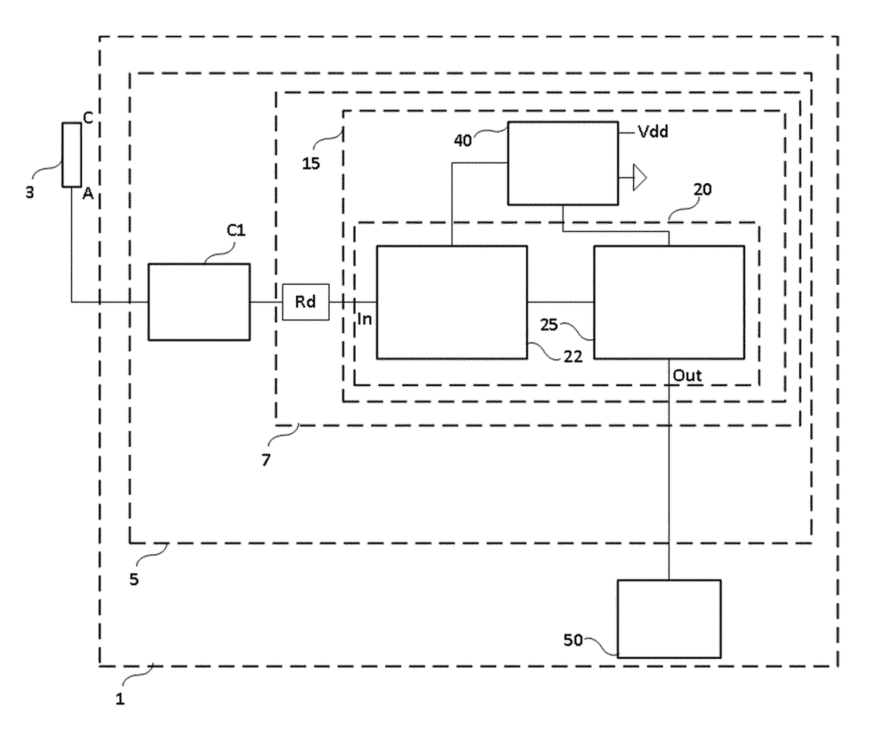
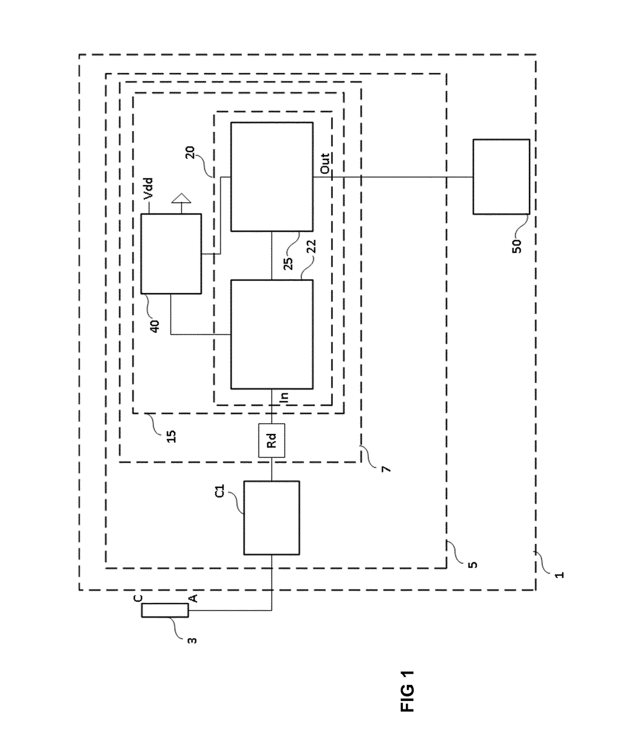
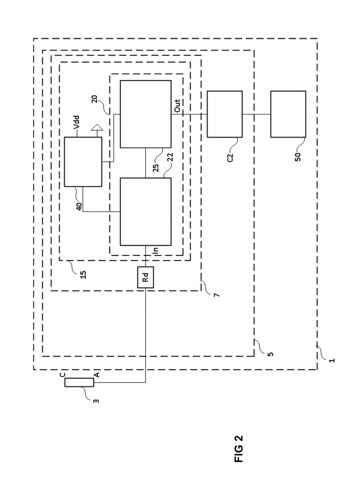
[0028]FIG. 1 is a block diagram of a summation circuit with a coefficient controller at the input, according to an example. Summation circuit 1 comprises readout circuit 5 and channel summing module 50. Readout circuit 5 comprises coefficient controller C1 and channel circuit 7. An input of coefficient controller C1 is coupled at one end to the anode A of photodiode 3 of a common cathode photomultiplier array. Photodiode 3 is a photodiode having an anode A and a cathode C. Channel circuit 7 comprises resistor Rd and input stage 15. Input stage 15 comprises current mirror circuit 20 and feedback circuit 40.

[0029]Resistor Rd is coupled at one end to an output of coefficient controller C1. The other end of resistor Rd is coupled, to an input (In) of current mirror circuit 20 of input stage 15. Current mirror circuit 20 shown in FIG. 1 comprises input branch 22 and output branch 25. An input of input branch 22 is the input of current mirror circuit 20. Input branch 22 and output branch ...


PUM


Abstract

A summation circuit (1) for summing one or more signals received from a photomultiplier array is proposed. The summation circuit comprises one or more readout circuits (5) coupleable to one or more photodiodes of the photomultiplier array (2), respectively, and a channel summing module (50), coupled at one or more outputs of the one or more readout circuits, respectively, to sum the one or more signals provided by the one or more readout circuits. The one or more readout circuits are coupleable to the photodiode of the photomultiplier array. Each readout circuit (5) comprises one or more coefficient controllers (C1, C2) for controlling multiplying coefficients of the received signal. The coefficient controllers may be placed at the input and / or at the output of the readout circuits (5).

Description

[0001]The present invention relates to summation configurations for multi-channel photomultiplier array signals.BACKGROUND ART[0002]Many circuits are known in the art for reading ultra sensitive photosensors such as photomultiplier tubes (PMT) or silicon photomultipliers (SiPM). PCT / EP2013 / 077305 discloses readout circuits for multi-channel photomultiplier common cathode arrays. The readout circuits are connectable to the anode of the photodiodes of the photomultiplier arrays. Using a feedback circuit, the resulting readout circuit is a wideband readout circuit with improved resolution of timing and energy measurements. However, the circuit disclosed in PCT / EP2013 / 077305 does not provide summation of the signals of the multiple channels.[0003]It is desirable to provide a summation circuit for photomultiplier arrays.SUMMARY OF THE INVENTION[0004]The terms “base”, “collector”, and “emitter” are typically used to describe the terminals of a bipolar junction transistor. Accordingly, the...

Claims


Application Information

Patent Timeline
Patent Type & Authority Applications(United States)
IPC IPC(8): G01J1/44G05F3/26
CPCG01J1/44G05F3/265G01J2001/4413G01J2001/4446H03F3/45076G05F3/26
Inventor GASCON FORA, DAVIDGOMEZ FERN NDEZ, SERGIOMAURICIO FERRE, JOAN
Owner UNIV DE BARCELONA
Learn More