
Laminated Body and Method of Producing Shaped Article

Active Publication Date: 2018-10-04
JX NIPPON MINING& METALS CORP
View PDF5 Cites 2 Cited by
  • Summary
  • Abstract
  • Description
  • Claims
  • Application Information

AI Technical Summary

Benefits of technology

The present invention makes it possible to create a thin and light laminated body with improved flexibility. This laminated body can be used for various packaging materials, as well as for electromagnetic wave shielding for electronic devices. It includes a metal foil component.

Problems solved by technology

The electromagnetic waves may cause erroneous operation of precision devices, and cause radio disturbance of on-board audio equipment, radio equipment and the like.
However, if the thickness of the metal sheet is reduced, then ductility will be decreased, which cause a problem that the metal sheet is broken during a molding process.
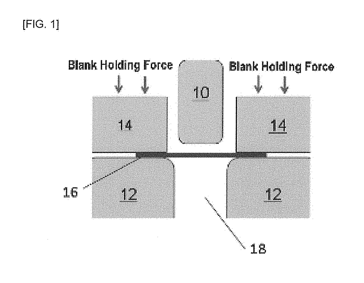
The drawing is a working method of forming bottomed containers having various shapes such as cylinders, square tubes, cones, and the like from a single metal sheet, which is said to be the highest degree of difficulty among press forming processes.
Further, if the material is thin at the inflow portion, the portion will buckle to form wrinkles.
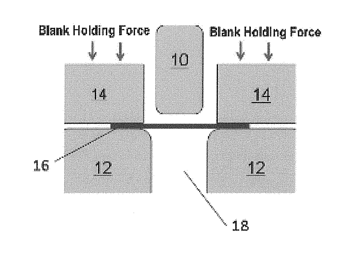
The increasing of the blank holding force results in increased friction between the mold and the molding material, increased resistance to material inflow, and easy breakage.
Accordingly, there has been a problem that for a thinner molding material, particularly a molding material having a thickness of 500 μm or less, wrinkles are generated in the side wall of the container when the blank holding force is small, whereas the molding material is broken when the blank holding force is larg.

Method used


Image

  • Laminated Body and Method of Producing Shaped Article
  • Laminated Body and Method of Producing Shaped Article

Examples


examples

[0076]Examples of the present invention are described below together with comparative examples, which are provided for better understanding of the present invention and its advantages, and are not intended to limit the invention.

(1. Preparation of Metal Foil)

[0077]The following materials were prepared as metal foils. The conductivity was measured by the double bridge method of JIS C 2525: 1999.

[0078]Cu: a rolled copper foil (electric conductivity at 20° C.: 58.0×10⁶ S / m; thickness: see Table 1); only in Example 14, an electrolytic copper foil (conductivity at 20° C.: 58.0×10⁶ S / m; thickness: see Table 1)

[0079]* For the rolled copper foil, “a pure copper foil” with no added element and “a copper alloy foil” with 0.2 wt % of Ag added, which decreased the 5% strain stress, were used. In should be noted that there is substantially no change in the conductivity because of the addition of a minor amount of Ag.

[0080]Al: an aluminum foil (conductivity at 20° C.: 39.6×10⁶ S / m; thickness: see...


PUM

PropertyMeasurementUnit
Fractionaaaaaaaaaa
Thicknessaaaaaaaaaa
Thicknessaaaaaaaaaa

Abstract

Provided is a laminated body of at least one metal foil and resin layers, which is suitable for drawing. The laminated body includes at least one metal foil and at least two resin layers. The laminated body has a thickness of 25 to 500 μm. In the laminated body, both surfaces of each metal foil are closely laminated to the resin layers, and the relationships: 60≤σY≤150, and 1.4≤σb / σY are satisfied, in which σY represents a nominal stress (MPa) at a nominal strain of 5% when a tensile test according to JIS K 7127: 1999 is performed on the laminated body, and σb represents a nominal stress (MPa) at a nominal strain at which the metal foil in the laminated body is broken when a tensile test according to JIS K 7127: 1999 is performed on the laminated body.

Description

TECHNICAL FIELD[0001]The present invention relates to a laminated body of at least one metal foil and resin layers, which is suitable for drawing. The present invention also relates to a method of producing a shaped article using the laminated body.BACKGROUND ART[0002]Recently, high attention has been widely focused on global environmental issues, and environmentally-friendly motor vehicles equipped with secondary batteries such as electric vehicles and hybrid vehicles have progressively prevailed. These motor vehicles often employ a mode of converting direct current generated from the mounted secondary battery into alternating current through an inverter, and then supplying required electric power to the alternating current motor to provide driving force. Electromagnetic waves are generated due to switching operation of the inverter and the like. The electromagnetic waves are emitted not only from the motor vehicles but also from many electric and electronic devices including commu...

Claims


Application Information

Patent Timeline
IPC IPC(8): B32B15/09H05K9/00B32B7/12B32B15/095B32B15/092B32B15/088
CPCB32B15/09H05K9/0088B32B7/12B32B15/095B32B15/092B32B15/088B32B2250/03B32B2367/00B32B2307/204B32B2307/202B32B2309/105B32B15/08B32B27/06B32B37/06B32B37/10B32B2307/212B32B15/20H05K9/0084B32B2250/40B32B2255/06B32B2255/26B32B2307/50B32B2307/732B32B2457/00B32B38/12B32B25/14B32B27/40B32B15/085B32B2255/10B32B2307/748B32B27/281B32B2262/106B32B2307/54B32B2307/208B32B27/36B32B27/304B32B2605/00B32B2307/712B32B27/283B32B27/365B32B25/04B32B2250/42B32B2262/101B32B2307/306B32B27/16B32B27/308B32B25/20B32B27/32B32B27/34B32B27/306B32B2255/205B32B15/06B32B27/302B32B15/082B32B27/38B32B25/16B32B2307/752B32B27/42B32B2262/0269B32B15/098B32B2037/0092
Inventor TANAKA, KOICHIRO
Owner JX NIPPON MINING& METALS CORP
Learn More