
Numerical controller of machine tool

Active Publication Date: 2018-08-23
FANUC LTD
View PDF0 Cites 1 Cited by
  • Summary
  • Abstract
  • Description
  • Claims
  • Application Information

AI Technical Summary

Benefits of technology

The present invention provides a numerical controller for a machine tool that can suppress heat generation and achieve stable position control. This is achieved by improving the control mode of the spindle motor, which is controlled by position control based on a position command, but sometimes needs to switch from speed control to position control to accelerate or decelerate the spindle motor. The invention aims to minimize these switches and provide a more efficient and stable control method.

Problems solved by technology

The induction motor has a drawback that heat is generated when an excitation current flows into the stator coil.
In this case, as described above, when the control mode is switched from speed control to position control to accelerate or decelerate the induction motor in a state in which a torque is decreased due to a weakened magnetic flux of the induction motor which is a spindle motor, since it is not possible to accelerate or decelerate the induction motor immediately with a maximum torque (acceleration), the induction motor cannot follow the position command.
Due to this, there is a possibility that a deviation amount with respect to a position command may increase, an overshoot of a spindle may occur, and a machining error may become too large.
Moreover, synchronization accuracy between the spindle motor and the feed axis motor may deteriorate.

Method used


Image

  • Numerical controller of machine tool
  • Numerical controller of machine tool
  • Numerical controller of machine tool

Examples


first embodiment

Advantages of First Embodiment

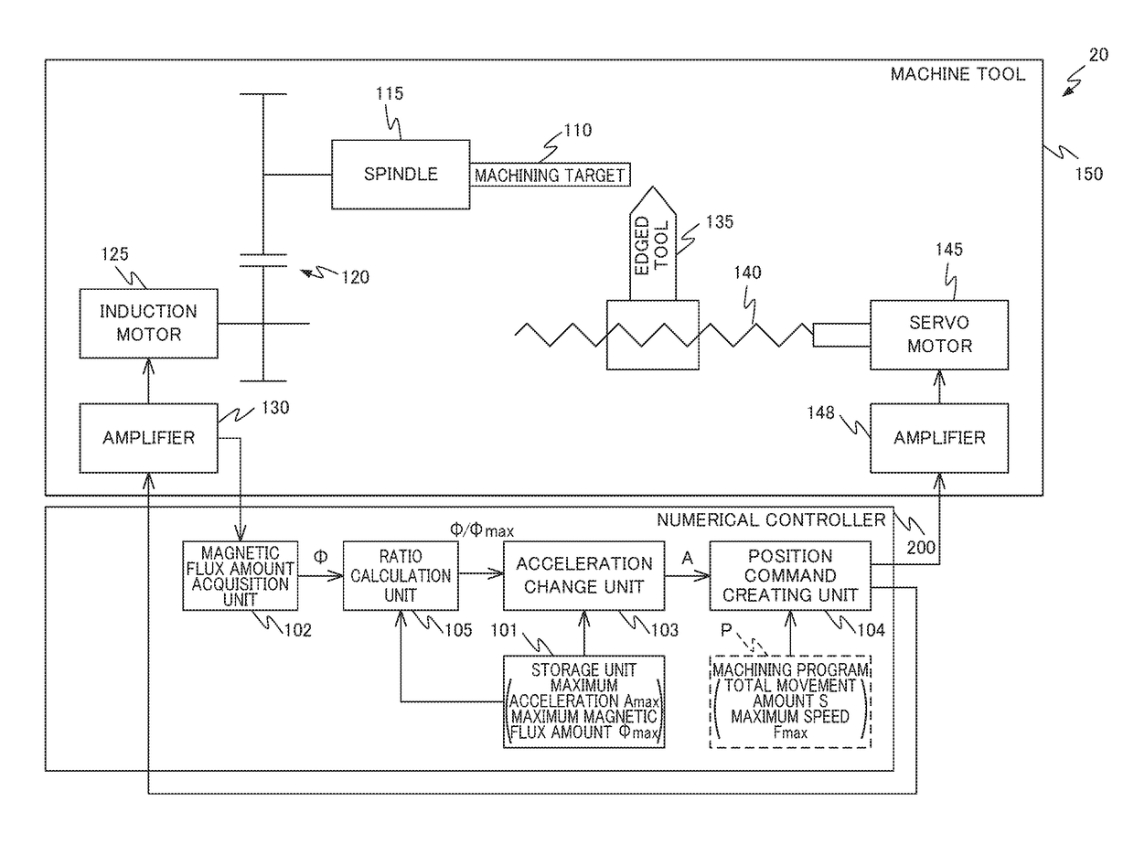
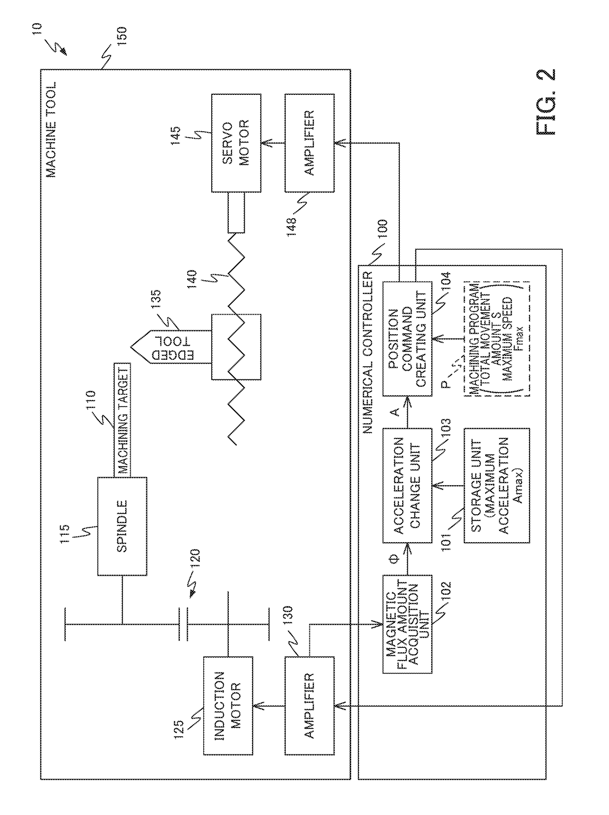
[0049]In the numerical control system 10 according to the first embodiment, when position control based on a position command is performed, by changing the acceleration of the position command of the induction motor 125 according to the magnetic flux amount of the induction motor 125, it is possible to suppress heat generation in a light load state of the induction motor 125 and realize stable position control during acceleration or deceleration of the induction motor 125.

[0050]Specifically, a case in which a technique of weakening a magnetic flux or an excitation current of a rotating magnetic field when a load on the induction motor 125 is light and a high torque is not required in a mode in which the induction motor 125 is controlled by speed control based on a speed command in order to avoid a drawback that heat is generated when an excitation current flows into a stator coil of the induction motor 125 is used will be considered.

[0051]When synchrono...

second embodiment

Advantages of Second Embodiment

[0063]In the numerical control system 20 according to the second embodiment, by changing the acceleration of the position command according to the magnetic flux amount of the induction motor 125, it is possible to suppress heat generation and realize stable position control similarly to the numerical control system 10 according to the first embodiment. Moreover, it is possible to suppress deterioration of the synchronization accuracy between the spindle motor and the feed axis motor. Moreover, when synchronous operation of the spindle motor and the feed axis motor is performed (that is, when the control mode of the induction motor 125 which is the spindle motor is switched from speed control to position control), it is possible to output the position command immediately and perform control of the induction motor 125.

[0064]While embodiments of the present invention have been described, the present invention is not limited to the above-described embodime...


PUM


Abstract

A numerical controller for controlling a machine tool including a spindle motor formed of an induction motor includes: a storage unit that stores a maximum acceleration at which the spindle motor can operate when a magnetic flux amount of the spindle motor reaches its maximum; a magnetic flux amount acquisition unit that acquires a present magnetic flux amount of the spindle motor; and an acceleration change unit that changes an acceleration of a position command based on a maximum acceleration of the spindle motor stored in the storage unit according to a magnetic flux amount at the start of movement of the spindle motor acquired by the magnetic flux amount acquisition unit when the spindle motor is operated by position control using a position command.

Description

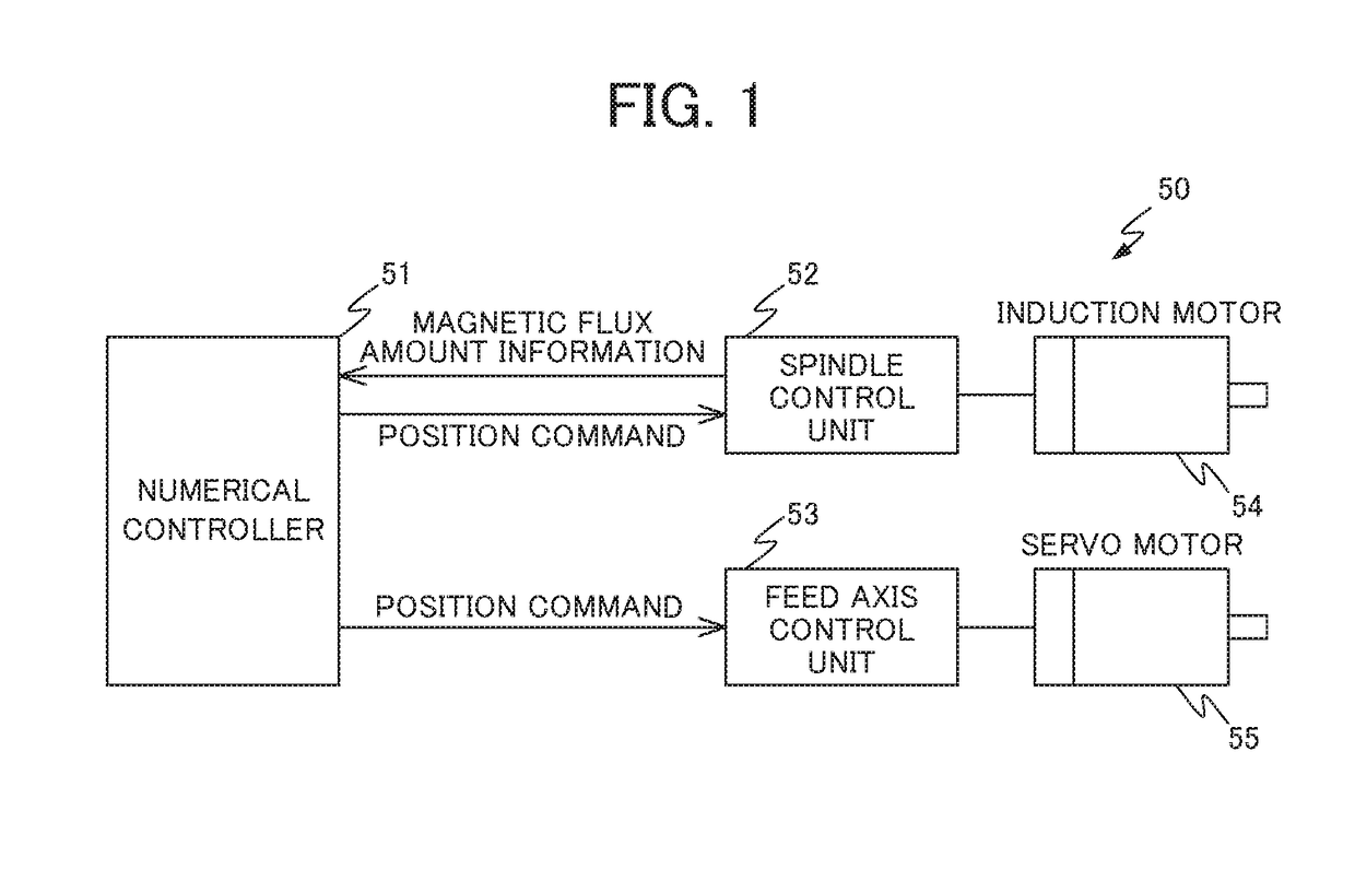
[0001]This application is based on and claims the benefit of priority from Japanese Patent Application No. 2017-031223, filed on 22 Feb. 2017, the content of which is incorporated herein by reference.BACKGROUND OF THE INVENTIONField of the Invention[0002]The present invention relates to a numerical controller of a machine tool including a spindle motor formed of an induction motor.Related Art[0003]When a work is machined using a machine tool having a spindle and a feed axis, the movement of the spindle is relatively often interlocked with the movement of the feed axis. In such a case, in a general numerical controller that controls a machine tool, a feed axis is controlled using a characteristic value or a measurement value associated with the spindle, or the spindle is controlled using a characteristic value or a measurement value associated with the feed axis.[0004]For example, Patent Document 1 discloses a technique of controlling a feed rate using data corrected using a change i...

Claims


Application Information

Patent Timeline
IPC IPC(8): G05B19/19
CPCG05B19/19H02P5/50G05B2219/42064G05B2219/37389G05B19/416G05B2219/34169H02P23/20G05B2219/49108G05B19/29
Inventor OIKAWA, KOUKIMORITA, YUUKIOKITA, TADASHI
Owner FANUC LTD
Learn More