
Liquid Ejection Apparatus, Control Method for the Same, and Computer-Readable Storage Medium

Active Publication Date: 2014-04-03
BROTHER KOGYO KK
View PDF0 Cites 4 Cited by
  • Summary
  • Abstract
  • Description
  • Claims
  • Application Information

AI Technical Summary

Benefits of technology

This patent is about a liquid ejection apparatus that can prevent the deterioration of its regulators and improve the quality of images recorded on a recording medium. The apparatus uses a method to control the voltage difference between the main voltage and the drive voltage, which reduces heat generation by the regulators. By creating a small ejection driving waveform, the apparatus can eject a smaller amount of ink than the amount of ink ejected according to a driving waveform created from image data, which helps to prevent deterioration of the image quality.

Problems solved by technology

If the voltage difference between the IN terminal and OUT terminal becomes too large, too much heat is generated by the three-terminal regulator, so the circuit of the three-terminal regulator may deteriorate.
Conversely, if the voltage difference is limited to a certain value, another problem occurs.

Method used


Image

  • Liquid Ejection Apparatus, Control Method for the Same, and Computer-Readable Storage Medium
  • Liquid Ejection Apparatus, Control Method for the Same, and Computer-Readable Storage Medium
  • Liquid Ejection Apparatus, Control Method for the Same, and Computer-Readable Storage Medium

Examples


Embodiment Construction

[0020]Example embodiments in which a liquid ejection apparatus is applied as an inkjet printer will be described with reference to the drawings.

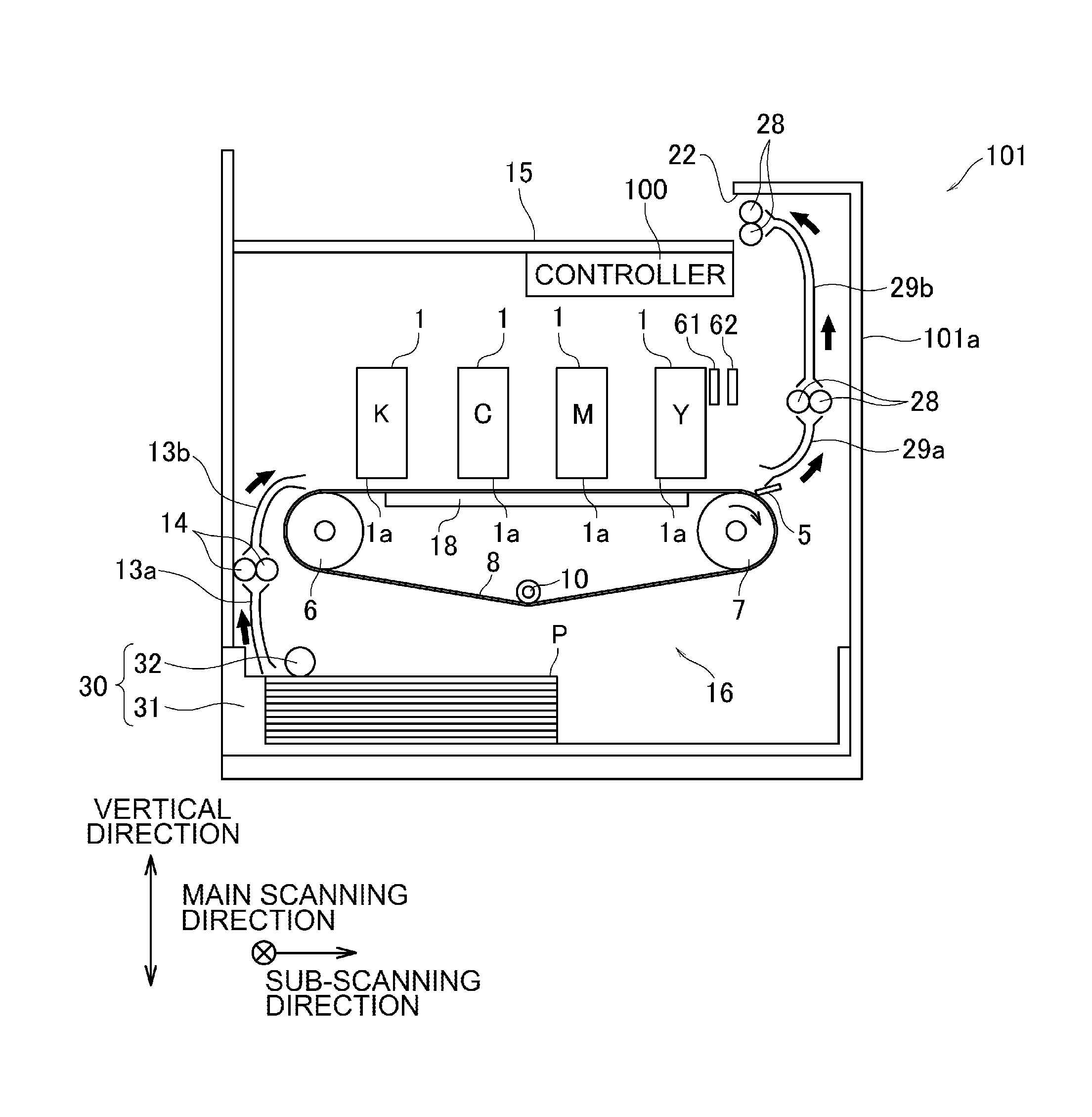
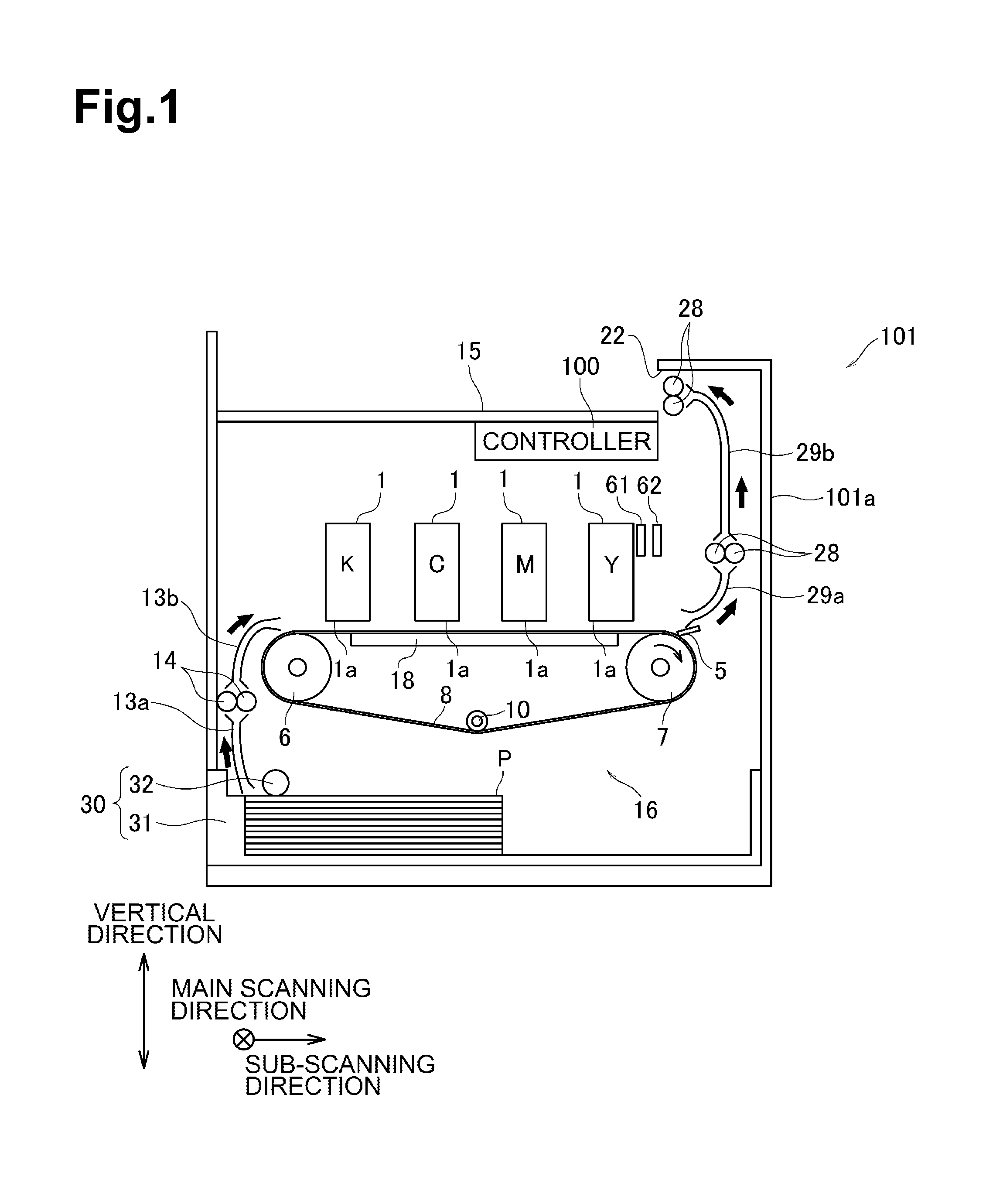
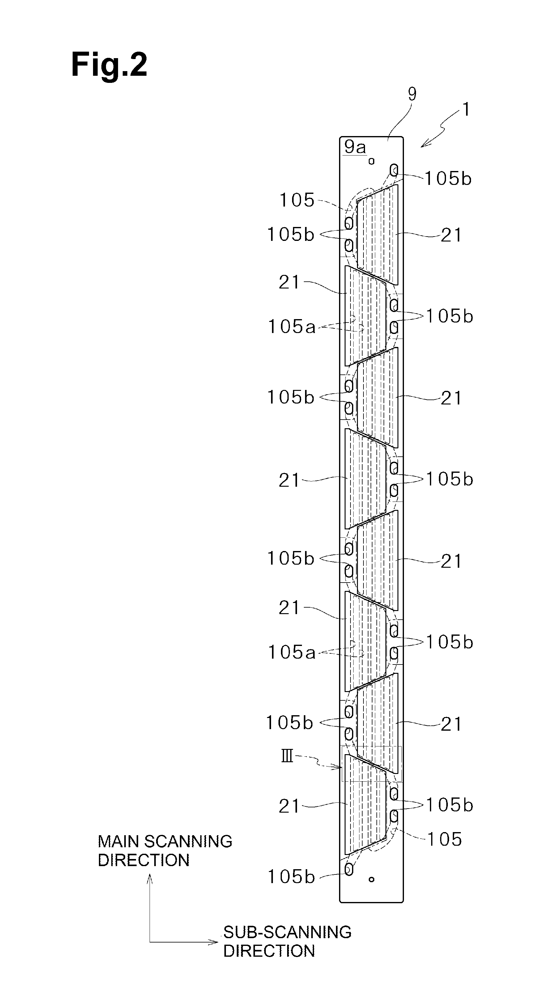
[0021]The entire structure of an inkjet printer 101 (simply referred to below as the printer 101) according to a first embodiment will be described first with reference to FIG. 1. The printer 101 has a case 101a in a rectangular parallelepiped shape as illustrated in FIG. 1. Four inkjet heads 1 (liquid ejection heads, which will be referred to below as heads 1), which eject ink in magenta, cyan, yellow, and black, and a conveyance mechanism 16 are placed in the case 101a. A controller 100 that controls the operation of the heads 1, the conveyance mechanism 16, and the like is attached to the inner surface of the top plate of the case 101a. A paper output tray 15 is placed on the upper surface of the top plate. Paper P on which an image has been created is discharged to the paper output tray 15. A paper feed mechanism 30, which can be attache...


PUM


Abstract

A liquid ejection apparatus includes a liquid ejection head, actuator units with actuators, a power supply that output a main voltage, and linear regulators that reduce the main voltage to drive voltages to be supplied to the relevant actuator units. When a voltage difference between the main voltage and drive voltage is greater than an allowable value for any of the actuator units, the apparatus controls a linear regulator so that the drive voltage supplied to at least one actuator unit is adjusted to a high drive voltage. A small ejection driving waveform is created as the driving waveform to be output to the actuators in the actuator unit to which the high drive voltage is supplied.

Description

CROSS REFERENCE TO RELATED APPLICATION[0001]This application claims priority from Japanese Patent Application No. 2012-218151, filed on Sep. 28, 2012, which is incorporated herein by reference.FIELD OF DISCLOSURE[0002]The disclosure herein relates to a liquid ejection apparatus, a method of controlling the liquid ejection apparatus, and a computer-readable storage medium for controlling liquid ejection.BACKGROUND[0003]A known printing head voltage controller lowers a main voltage output from a switching power supply apparatus by using a printing head voltage control circuit to obtain driving voltages on which a plurality of printing heads operate. This type of voltage controller uses an inexpensive three-terminal regulator in the printing head voltage control circuit. To obtain a stable output, a voltage difference between the IN terminal and OUT terminal of the three-terminal regulator is set to a fixed voltage (1.5 V, for example) or higher.BRIEF SUMMARY[0004]If the voltage differ...

Claims


Application Information

Patent Timeline
IPC IPC(8): B41J2/07
CPCB41J2/07B41J2/04551B41J2/04553B41J2/04566B41J2/04581B41J2/04588B41J2/04595B41J2/14209B41J2002/14459B41J2202/20
Inventor UCHINO, SHUNJI
Owner BROTHER KOGYO KK
Learn More