Self-piercing rivet with high mechanical strength against tearing out and shearing

a rivet and mechanical strength technology, applied in the direction of threaded fasteners, screws, fastening means, etc., can solve the problems of rivets still presenting mechanical strength weaknesses, not enabling optimal reinforcement of self-drilling anchors, and not satisfying manufacturers' types of self-drilling anchors. to achieve the effect of increasing speed

Inactive Publication Date: 2018-08-23
A RAYMOND & CO
View PDF0 Cites 2 Cited by
  • Summary
  • Abstract
  • Description
  • Claims
  • Application Information

AI Technical Summary

Benefits of technology

The invention provides a rivet that is stronger than existing rivets used in automotive assembly. It can be easily assembled and can be used with floor mats. The rivet is designed to ensure sealing between the plates and can also contain any dust or debris caused by piercing. Overall, the rivet is more durable and easier to use in automotive assembly.

Problems solved by technology

However, in the automotive industry those types of self-drilling anchor do not satisfy manufacturers since they have low shearing and tearing strengths, especially in the event of an impact.
However, after the tool has been removed, a through orifice made by the tool is left unfilled, which does not enable the structure of the self-drilling anchor to be reinforced in optimal manner in order to improve strength.
However, after piercing, those rivets still present weaknesses in terms of mechanical strength.
However, when those rivets are used to pierce composite elements, the anchors or rivets do not make it possible to make “clean” holes since, during piercing, they often lead to delamination and to fibers being torn, as well as to uncontrolled discharge of dust.
In addition, after the plates have been assembled together, the axial traction exerted on the rod leads to the rod breaking for an appropriate value of traction on the breakable zone in such a manner that the broken rod does not extend past the flange.

Method used


Image

  • Self-piercing rivet with high mechanical strength against tearing out and shearing
  • Self-piercing rivet with high mechanical strength against tearing out and shearing

Examples


Embodiment Construction

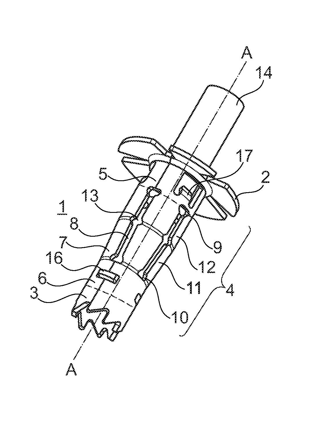
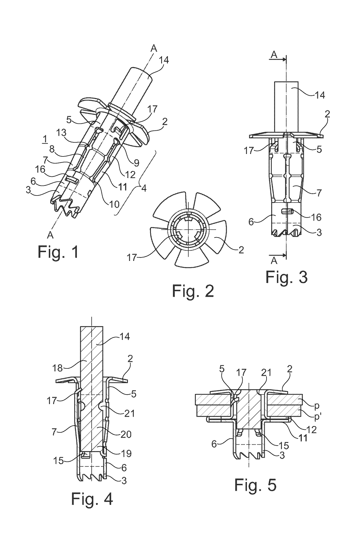
[0036]FIGS. 1 to 5 show a rivet 1 of the invention for assembling two plaques (P and P′ shown in FIG. 5). By way of non-limiting example, the plates may be fiberglass plates.

[0037]The rivet 1 includes a flange 2, coming to bear for example on one of the plates to be assembled, and a piercing end 3.

[0038]The flange 2 extends in a plane that is perpendicular to an axis AA of the rivet 1. The flange 2 may have tabs (not shown) that bite into the bearing surface in order to prevent it from moving in axial rotation.

[0039]In this embodiment, the piercing end 3 is of the double-toothed circular hole saw type. The hole saw includes an inside bore with teeth distributed circumferentially about the bore in order to reduce dust and fiber-tearing during piercing.

[0040]Without going beyond the ambit of the invention, the piercing end could be of the drill-bit type with a diamond coating (not shown).

[0041]Between the flange 2 and the piercing end 3, the rivet 1 presents a barrel-shaped tubular bo...


PUM


Abstract

A self-piercing rivet comprising a bearing flange and a piercing end with an expandable hollow tubular body extending axially between the flange and the piercing end, the body comprising a cylindrical first portion that is adjacent to the flange, a cylindrical second portion that is adjacent to the piercing end, and a radially-expandable third portion between said cylindrical first and second portions, the rivet further comprises a breakable rod that extends axially inside the hollow body to drive the body in axial rotation and to deform it radially at said expandable third portion under the effect of axial traction. The third portion (7) of the body is designed to produce, before being deformed radially, an abrasion or deburring effect on the peripheral edge of a hole being pierced by the piercing end.

Description

[0001]This application is a 371 national phase entry of PCT / FR2016 / 052692, filed 18 Oct. 2016, which claims benefit of French Patent Application No. 1560262, filed 27 Oct. 2015, the entire contents of which are incorporated herein by reference for all purposes.TECHNICAL FIELD[0002]The invention relates to a self-piercing rivet comprising a bearing flange and a piercing end, with a radially-expandable hollow tubular body extending axially between the flange and the piercing end, the tubular body comprising a cylindrical first portion that is adjacent to the flange, a cylindrical second portion that is adjacent to the piercing end, and an expandable barrel-shaped third portion between the cylindrical first and second portions, the rivet further comprising a rod that extends axially inside the hollow body.RELATED ART[0003]It is known to use a self-drilling expansion anchor to assemble two elements in simple manner, such as assembling a part to a support.[0004]Documents FR 2 927 382 and...

Claims


Application Information

Patent Timeline
IPC IPC(8): F16B19/08F16B19/10
CPCF16B19/083F16B19/086F16B19/1054F16B19/08
Inventor COCHARD, MATHIEUFENOLL, JONATHANDEPAIL, YVES-MARIE
Owner A RAYMOND & CO
Why Eureka
Try Eureka