Inspection vehicle

a technology for inspection vehicles and hulls, applied in the direction of image data processing, cameras, electrical/magnetic measuring arrangements, etc., can solve the problems of deteriorating structural integrity, new coating systems, and less effective, and achieve the effect of reducing the emission of greenhouse gases

Inactive Publication Date: 2018-08-16
ECOSUBSEA
View PDF8 Cites 7 Cited by
  • Summary
  • Abstract
  • Description
  • Claims
  • Application Information

AI Technical Summary

Benefits of technology

The invention is a special inspection vehicle designed to roll over the hull of a ship to inspect it for marine growth. The vehicle has wider and heavier wheels at the bottom than at the top, making it easier to roll and orient. It uses magnetic wheels to prevent the vehicle from tipping over when flat. The non-magnetic part of the vehicle has a structure that prevents magnetic coupling to the wheels. The use of the inspection vehicle can save fuel and reduce emissions of greenhouse gases by providing information on when to clean the ship hull. The vehicle can easily move over marine growth and follow the curvature of the hull. It can be transported easily and operated with one person. The vehicle is designed to be strong enough to be used in any foreseeable situation.

Problems solved by technology

Deterioration of the coating on a structure enhances corrosion, which eventually deteriorates the structural integrity.
Experience show that new coating systems, after tin was removed as a component from anti-foulings in 2008, are less effective, which may be a result of less effective but also less poisonous and health threatening antifouling agents or additives in recent years, since many substances and compositions have been prohibited or restricted.
Typically, divers or ROVs (Remotely Operated Vehicles) must be hired in order to undertake a visual control, and in most harbors the service is not readily available.

Method used


Image

  • Inspection vehicle
  • Inspection vehicle
  • Inspection vehicle

Examples


Embodiment Construction

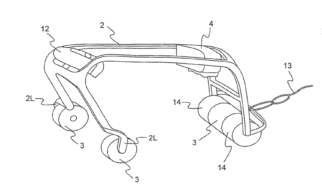
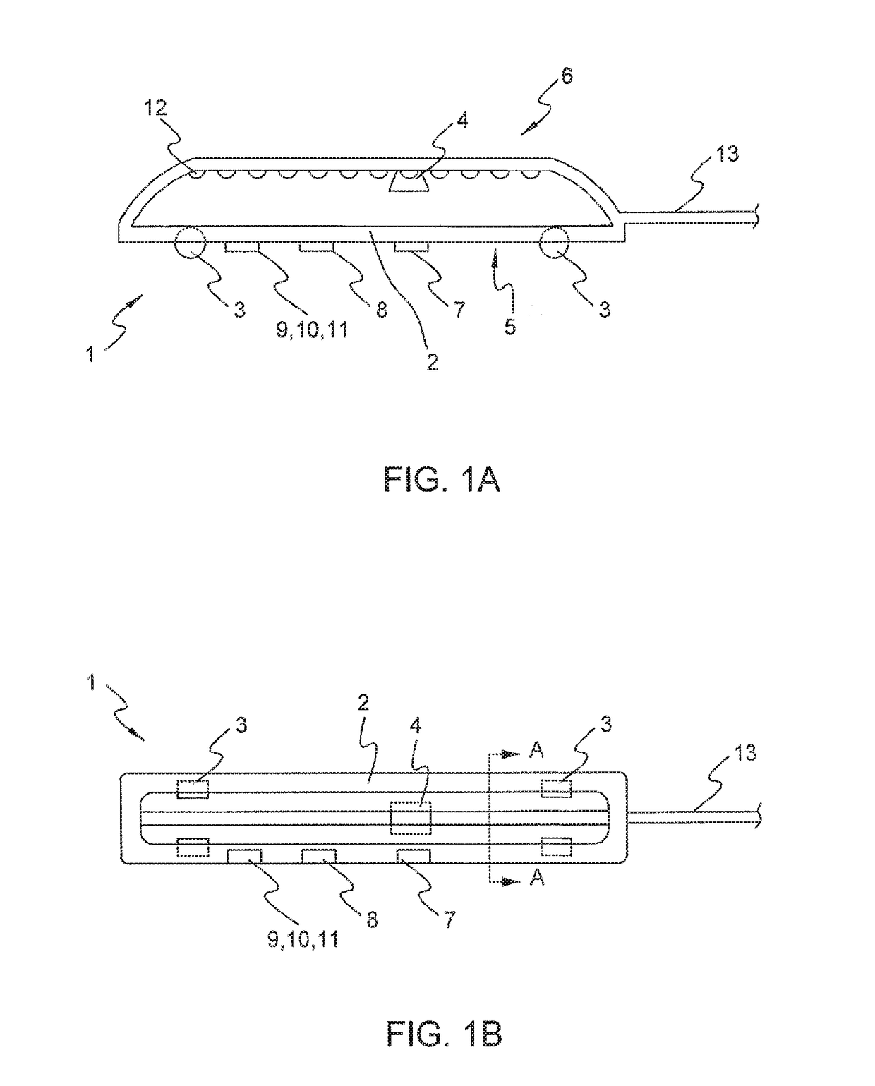
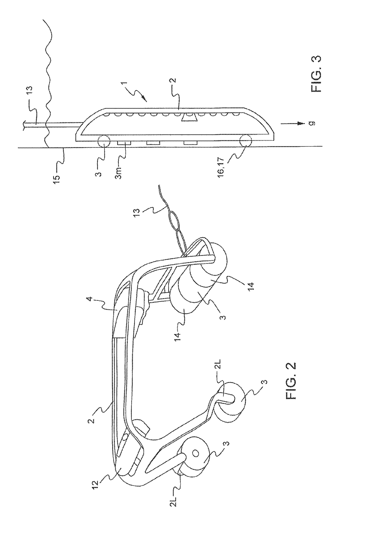
[0075]Reference is made to FIGS. 1A and 1B, illustrating an inspection vehicle of the invention, as seen from the side and from above, respectively. More specifically, the inspection vehicle (1) for under water inspection of coating, marine growth, structural integrity and corrosion on ferromagnetic ship hulls and other ferromagnetic structures, above and below water comprises a non-magnetic element (2), at least one magnetic wheel (3) operatively arranged to the element, and a watertight camera (4) for visual inspection attached to the element or other structure of the inspection vehicle. The inspection vehicle further comprises one coupling side (5) where the at least one magnetic wheel is operatively arranged for the inspection vehicle to couple magnetically and allow rolling the inspection vehicle on said structure, through coating, marine growth and corrosion, in horizontal to vertical to upside down-orientation while holding the inspection vehicle attached to the structure; an...


PUM


Abstract

Inspection vehicle (1) for under water inspection of coating, marine growth, structural integrity and corrosion on ferromagnetic ship hulls and other ferromagnetic structures. The inspection vehicle is distinctive in that it comprisesa non-magnetic element (2),at least one magnetic wheel or device (3) operatively arranged to the element, anda watertight camera (4) for visual inspection attached to the element or other structure of the inspection vehicle,wherein the inspection vehicle comprisesone coupling side (5) where the at least one magnetic wheel or device is operatively arranged for the inspection vehicle to couple magnetically through coating, any marine growth and corrosion products and allow rolling the inspection vehicle on said structure, in horizontal to vertical to upside down-orientation while holding the inspection vehicle attached to the structure, andone non-coupling side (6) oriented in substance in opposite direction to the coupling side, where the at least one magnetic wheel is not operatively arranged and the non-coupling side will not couple magnetically to said structure.A method for operating the inspection vehicle is also provided.

Description

FIELD OF THE INVENTION[0001]The present invention relates to inspection of ship hulls and other structure. More specifically, the invention relates to inspection vehicle for under water inspection of coating, marine growth, structural integrity and corrosion on ferromagnetic ship hulls and other ferromagnetic structures.BACKGROUND OF THE INVENTION AND PRIOR ART[0002]Coating protects ship hulls and other structures at sea and on shore.[0003]Deterioration of the coating on a structure enhances corrosion, which eventually deteriorates the structural integrity. Experience show that new coating systems, after tin was removed as a component from anti-foulings in 2008, are less effective, which may be a result of less effective but also less poisonous and health threatening antifouling agents or additives in recent years, since many substances and compositions have been prohibited or restricted.[0004]Marine growth has a surprising large effect on fuel consumption of a ship. The friction of...

Claims


Application Information

Patent Timeline
IPC IPC(8): G06T7/00B60R11/04B60B19/00B62D63/02G03B17/08G01N17/04G01N27/82G01B17/02
CPCG06T7/0004B60R11/04B60B19/006B62D63/02G06T2207/30252G01N17/04G01N27/82G01B17/02G06T2207/30156G03B17/08G01B7/06B62D57/04B60Y2200/47
Inventor OSTERVOLD, TOR MIKALOSTERVOLD, KLAUS
Owner ECOSUBSEA
Why Eureka
Try Eureka