Torque wrench structure

a technology of torque wrench and torque transmission, which is applied in the direction of wrenches, screwdrivers, manufacturing tools, etc., can solve the problems of affecting reducing the amount of lubrication oil, and reducing the lubrication effect, so as to improve the sliding motion of the resisting member, enhance the torque transmission effect of the torque wrench, and reduce the friction therebetween

Inactive Publication Date: 2018-08-16
OGC TORQUE
View PDF5 Cites 5 Cited by
  • Summary
  • Abstract
  • Description
  • Claims
  • Application Information

AI Technical Summary

Benefits of technology

[0014]With such configuration, by use of the sleeve member disposed between the outer tube and the resisting member, with the non-consecutive contact relationship between the contacting portion of the sleeve member and the resisting member, the contacting square measure between the resisting member and the sleeve member is reduced, so as to lower the friction therebetween. Therefore, during the operation of the torque wrench, the sleeve member is provided with additional lubrication effect, whereby the smoothness of the sliding motion of the resisting member is improved, enhancing the torque transmission of the torque wrench. Further, when the lubrication oil is added to the resisting member, the helix shaped structure of the contact portion provides a storage space of the lubrication oil. Therefore, the necessity of regularly disassembling the torque wrench for adding the lubrication oil therein is saved, and the operation of the torque wrench is facilitated with only a small amount of lubrication oil.
[0015]In addition, during the manufacturing process of the outer tube of the present invention, the thermal processing step is allowed to be saved. The thermally-processed sleeve member fulfills the hardness and rigidity requirement of the outer tube, such that the thermal deformation issue of the outer tube during the manufacturing procedure is improved.
[0016]Also, the outer diameter of the aligning portion of the resisting member axially tapers away from the outer tube, so as to align the central point of the resilient member, and prevent the resilient member from deviating during the operation of the torque wrench, thus improving the torque transmission of the torque wrench.

Problems solved by technology

However, the amount of the lubrication oil decreases as the time goes by, causing the lubrication effect to become lower.
As a result, the torque transmission effect of the torque wrench is adversely affected.
However, a gap is thereby produced between the screw stud and the compression spring.
As a result, the compression spring is unable to be mounted around the screw stud and disposed in alignment with the axis of the screw stud, such that elements possibly shake.
As a result, a negative effect is imposed upon the torque transmission of the torque wrench.
However, during the thermal processing, a thermal deformation possibly occurs, causing the hollow tube to be bent and deformed.
As a result, the inner diameter of the hollow tube is unable to be consistent.
When the compression spring is disposed in the hollow tube, during the operation of the torque wrench, the center of the compression spring deviates from the axial center of the hollow tube, and the torque transmission of the torque wrench is easily affected.

Method used


Image

  • Torque wrench structure
  • Torque wrench structure
  • Torque wrench structure

Examples


Embodiment Construction

[0023]The aforementioned and further advantages and features of the present invention will be understood by reference to the description of the preferred embodiment in conjunction with the accompanying drawings where the components are illustrated based on a proportion for explanation but not subject to the actual component proportion.

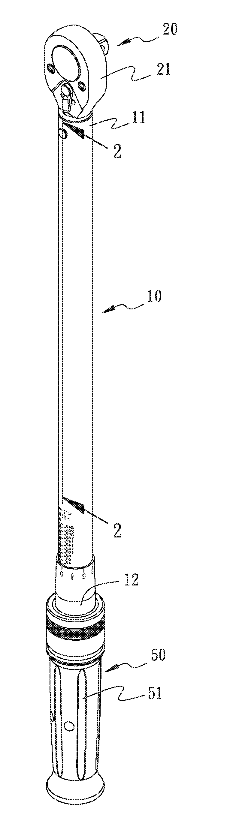
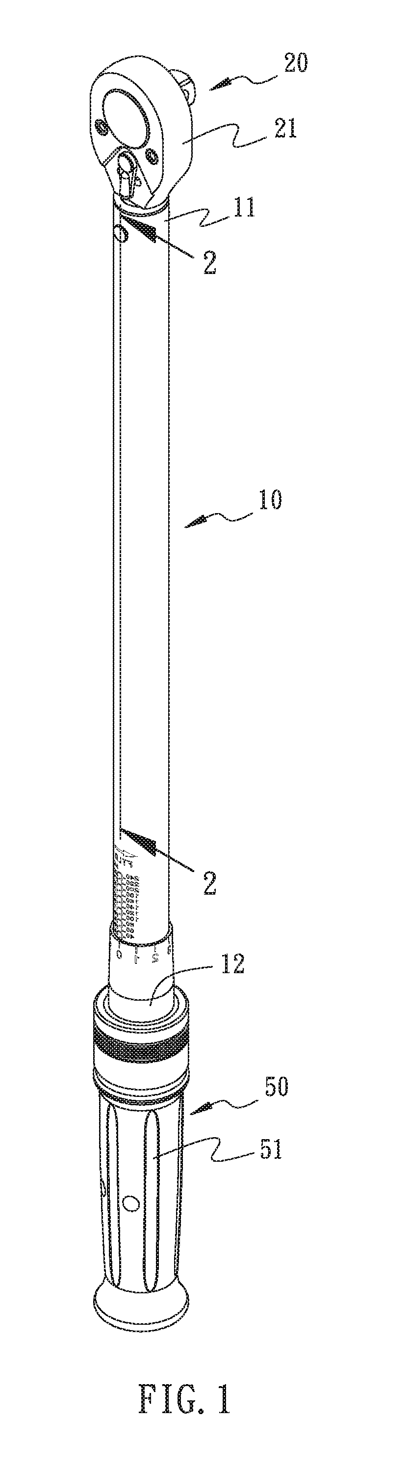
[0024]Referring to FIG. 1 to FIG. 6, a torque wrench structure in accordance with an embodiment of the present invention comprises an outer tube 10, a driving member 20, a resisting member 30, a sleeve member 40, and a torque adjusting device 50.

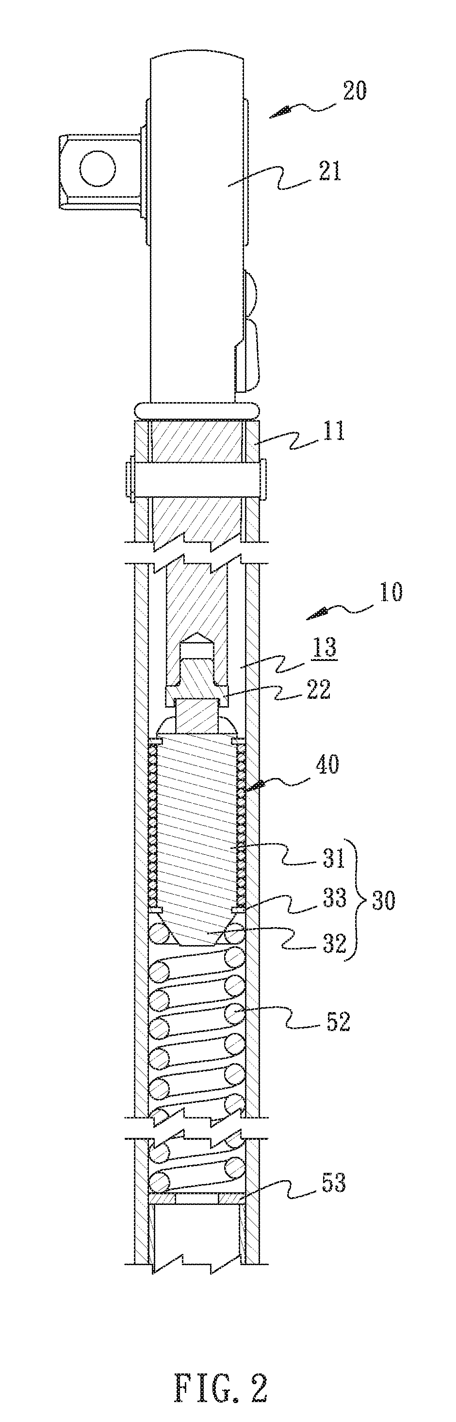
[0025]The outer tube 10 is provided with a front end 11 and a rear end 12, and a housing space 13 is axially disposed in the outer tube 10.

[0026]The driving member 20 has one end thereof provided with a driver 21 and the other end thereof provided with a connecting end 22. The driving member 20 is disposed at the front end 11 of the outer tube 10. The connecting end 22 is inserted into the housing space 13. The...


PUM


Abstract

A torque wrench structure includes an outer tube, a driving member, a resisting member, a sleeve member, and a torque adjusting device. The outer tube is provided with an axially disposed housing space. The driving member has one end provided with a driver and the other end provided with a connecting end, wherein the connecting end is disposed at one end of the outer tube and inserted into the housing space. The resisting member is slidably disposed in the housing space and connected with the connecting end. The sleeve member is disposed between the outer tube and the resisting member. The torque adjusting device is disposed at one end of the outer tube away from the driver, so as to be operated to adjust the torque value.

Description

BACKGROUND OF THE INVENTION1.Field of the Invention The present invention relates to tools, and more particularly, to a torque wrench structure.2.Description of the Related Art[0001]As shown by U.S. Pat. No. 8,245,606, a torque wrench is disposed, comprising a hollow tube; a driving rod pivotally disposed in the hollow tube and providing with a driver; a roller carrier slidably disposed in the hollow tube and pivotally connected with one end of the driving rod away from the driver; a screw stud combined with the roller carrier; a compression spring mounted around a protrusion of the screw stud; and an adjustment device disposed at another end of the hollow tube away from the driving rod for resisting against the compression spring, such that the compression level of the compression spring is adjusted by use of the thread, thereby adjusting the torque of the torque wrench.[0002]During the operation of the torque wrench, the screw stud slides in the hollow tube as a feedback due to th...

Claims


Application Information

Patent Timeline
Patent Type & Authority Applications(United States)
IPC IPC(8): B25B23/142
CPCB25B23/1427B25B13/06B25B23/00
Inventor GUO, WUN-JIN
Owner OGC TORQUE
Why Eureka
Try Eureka