Exhaust treatment system and method for treatment of an exhaust gas stream

a technology of exhaust gas and treatment system, which is applied in the direction of exhaust treatment electric control, separation process, machines/engines, etc., can solve the problems of large substrate volume, increased cost, and difficulty in controlling temperature and temperature and the nosub>2/sub>/nosub>x /sub>over the reduction catalyst, etc., to achieve enhanced exhaust treatment system performance, reduced loss, and increased back pressure

Active Publication Date: 2018-08-09
SCANIA CV AB
View PDF12 Cites 2 Cited by
  • Summary
  • Abstract
  • Description
  • Claims
  • Application Information

AI Technical Summary

Benefits of technology

[0010]To some extent, the performance of the exhaust treatment system may be enhanced by increasing the substrate volumes comprised in the exhaust treatment system, which in particular reduces losses due to uneven distribution of the exhaust flow through the substrate. At the same time, a larger substrate volume provides a greater back pressure, which may counteract gains in fuel efficiency due to the higher conversion degree. Larger substrate volumes also entail an increased cost. It is thus important to be able to use the exhaust treatment system optimally, for example by avoiding over-sizing and / or by limiting the exhaust treatment system's spread in terms of size and / or manufacturing cost.

Problems solved by technology

Larger substrate volumes also entail an increased cost.
At a low temperature over the reduction catalyst, the reduction of nitrogen oxides NOx is typically ineffective.
The temperature and the NO2 / NOx fraction over the reduction catalyst are, however, generally difficult to control, since they to a great extent depend on a number of factors, such as how the driver drives the vehicle.
Thus, at for example cold starts and at vehicle operation with temperature- and / or flow transient elements, the function of the reduction catalyst deteriorates, and accordingly the reduction of nitrogen oxides NOx also deteriorates.
This deterioration may result in a poor exhaust purification, risking unnecessary pollution of the environment.
Additionally, because of the deterioration of the reduction catalyst's function, the risk of not achieving the regulatory requirements relating to exhaust purification increases.
Fuel consumption may also be adversely impacted by the deteriorating function, since fuel energy may then need to be used in order to increase the temperature and efficiency of the reduction catalyst, via different temperature increasing measures.

Method used


Image

  • Exhaust treatment system and method for treatment of an exhaust gas stream
  • Exhaust treatment system and method for treatment of an exhaust gas stream
  • Exhaust treatment system and method for treatment of an exhaust gas stream

Examples


Embodiment Construction

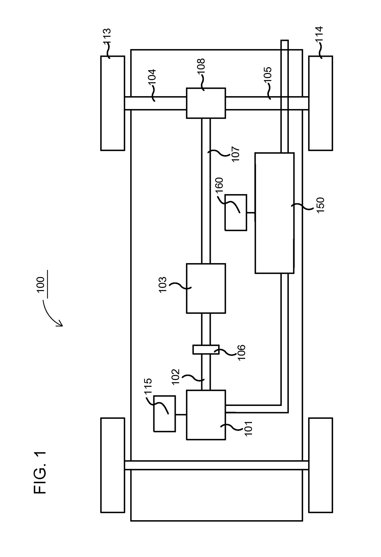
[0051]FIG. 1 schematically shows an example vehicle 100 comprising an exhaust treatment system 150, which may be an exhaust treatment system 150 according to one embodiment of the present invention. The power-train comprises a combustion engine 101, which in a customary manner, via an output shaft 102 on the combustion engine 101, usually via a flywheel, is connected to a gearbox 103 via a clutch 106.

[0052]The combustion engine 101 is controlled by the engine's control system via a control device 115. Likewise, the clutch 106 and the gearbox 103 may be controlled by the vehicle's control system, with the help of one or more applicable control devices (not shown). The vehicle's power-train may also be of another type, such as a type with a conventional automatic gearbox, of a type with a hybrid power-train, etc.

[0053]An output shaft 107 from the gearbox 103 drives the wheels 113, 114 via a final drive 108, such as e.g. a customary differential, and the drive shafts 104, 105 connected...


PUM


Abstract

An exhaust treatment system arranged for treatment of an exhaust stream is presented. The exhaust treatment system comprises a first reduction catalyst device arranged for reduction of nitrogen oxides in said exhaust stream through the use of compounds comprising one or several of carbon monoxide and hydrocarbons, which are comprised in said exhaust stream when said exhaust stream reaches said first reduction catalyst device; a particulate filter which is arranged downstream of said first reduction catalyst device to catch and oxidize soot particles in said exhaust stream; a second dosage device arranged downstream of said particulate filter and arranged to supply an additive comprising ammonia or a substance from which ammonia may be extracted and/or released into said exhaust stream; and a second reduction catalyst device, arranged downstream of said second dosage device and arranged for reduction of nitrogen oxides in said exhaust stream through the use of said additive.

Description

CROSS-REFERENCE TO RELATED APPLICATION(S)[0001]This application is a national stage application (filed under 35 § U.S.C. 371) of PCT / SE2016 / 050796, filed Aug. 25, 2016 of the same title, which, in turn claims priority to Swedish Application No. 1551109-0, filed Aug. 27, 2015 of the same title; the contents of each of which are hereby incorporated by reference.FIELD OF THE INVENTION[0002]The present invention relates to an exhaust treatment system, a method, and computer program product for treatment of an exhaust.BACKGROUND OF THE INVENTION[0003]The following background description constitutes a description of the background to the present invention, and thus need not necessarily constitute prior art.[0004]In connection with increased government interests concerning pollution and air quality, primarily in urban areas, emission standards and regulations regarding emissions from combustion engines have been drafted in many jurisdictions.[0005]Such emission standards often consist of r...

Claims


Application Information

Patent Timeline
Patent Type & Authority Applications(United States)
IPC IPC(8): B01D53/94F01N13/00F01N3/035F01N3/20F01N3/10
CPCB01D53/9477B01D53/9495F01N13/009F01N3/035F01N3/208F01N3/103F01N2250/02F01N2610/02F01N11/005F01N2900/1602F01N3/021F01N3/106F01N3/108F01N3/2066F01N3/36F01N9/00F01N3/0231F01N2430/08F01N2610/03F01N2900/0416F01N2900/08Y02T10/12Y02T10/40B01D53/9418B01D53/9422B01D53/9459F01N3/206
Inventor NILSSON, MAGNUSBIRGERSSON, HENRIK
Owner SCANIA CV AB
Why Eureka
Try Eureka