
Motor stop control method and motor stop control apparatus

Active Publication Date: 2018-07-26
NIDEC COPAL CORPORATION +1
View PDF4 Cites 4 Cited by
  • Summary
  • Abstract
  • Description
  • Claims
  • Application Information

AI Technical Summary

Benefits of technology

The present invention provides a way to stop a motor from going too far, and a way to stop it in a stable position. This can help to improve the accuracy and efficiency of motor control.

Problems solved by technology

In this case, when the current speed of the motor does not satisfy the target speed value at the stop start stored in advance (recorded in a profile), the behavior thereof is likely not to be stable in some cases.

Method used


Image

  • Motor stop control method and motor stop control apparatus
  • Motor stop control method and motor stop control apparatus
  • Motor stop control method and motor stop control apparatus

Examples


first embodiment

[0015]First, a motor stop control apparatus configured to carry out a motor stop control method will be described before the motor stop control method according to an embodiment is described. Note that, in the embodiment, a case in which the motor stop control apparatus is applied to a radio control unit, a servo module product for a hobby robot, and the like will be described.

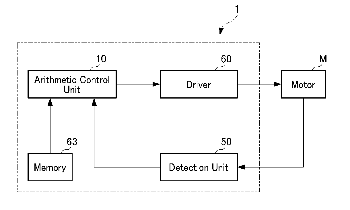
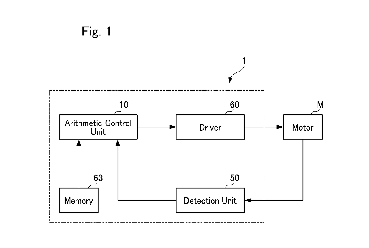
[0016]As shown in FIG. 1, a motor stop control apparatus 1 includes an arithmetic control unit 10 configured to control a motor M and a detection unit 50 capable of detecting a rotational state of the motor M. In the embodiment illustrated in FIG. 1, the motor stop control apparatus 1 further includes a driver 60 and a memory 63.

[0017]As shown inFIG. 3, the arithmetic control unit 10 has a stop start position Ps at which stop control is started from a position which is a predetermined angle θ before a target position Pt at which the motor M stops. The stop start position Ps is a position in front of the target...

second embodiment

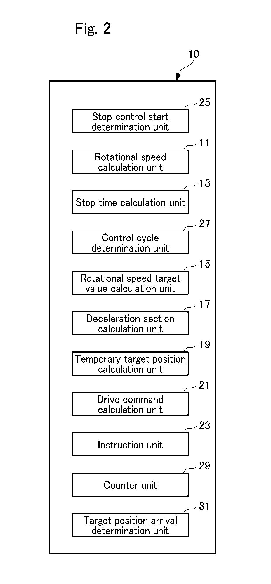
[0056]A second embodiment of the present invention will be described below. In the second embodiment, differences from the above-described first embodiment will be described, constituent elements which are the same as those of the first embodiment will be denoted with the same reference numerals, and description thereof will be omitted.

[0057]FIG. 6 is a diagram for describing a motor stop control method according to the second embodiment of the present invention.

[0058]As shown in FIGS. 2 and 6, the motor stop control method according to the second embodiment and the motor stop control method according to the first embodiment differ in which the motor stop control method according to the second embodiment performs, by an arithmetic control unit 10, a deceleration line calculation step and a rotational speed target value calculation performed step on the basis of the calculated deceleration line. The motor stop control method according to the embodiment further includes a deceleration...


PUM


Abstract

According to an aspect of the invention, a motor stop control method of a motor stop control apparatus which includes an arithmetic control unit and a detection unit. The arithmetic control unit has a stop start position at which a stop control is started from a position which is a predetermined angle before a target position at which a motor stops. The arithmetic control unit calculates a rotational speed of the motor at the stop start position on the basis of a detection value of the detection unit, and a stop time at which the rotational speed of the motor reaches zero from the stop start position on the basis of a deceleration line indicating a change in the rotational speed of the motor, the rotational speed of the motor, and the predetermined angle.

Description

CROSS-REFERENCE TO RELATED APPLICATION[0001]This application claims the benefit of Japanese Patent Application No. 2017-8498 filed on Jan. 20, 2017, which is hereby incorporated by reference herein in its entirety.BACKGROUND OF THE INVENTIONField of the Invention[0002]The present invention relates to a motor stop control method and a motor stop control apparatus.Description of the Related Art[0003]As a method for stopping a motor at a target position, for example, Japanese Patent 4212414 includes a speed control method in which a target speed value of a motor is determined as a control target value and a difference between a current speed of the motor and the control target value is made zero.[0004]In the motor stop control method disclosed in Japanese Patent 4212414, a target speed value calculated in advance for each sampling interval from start to stop of the stop control performed on the motor is stored in a memory. Moreover, an arithmetic control unit configured to control an o...

Claims


Application Information

Patent Timeline
IPC IPC(8): H02P3/06G05B19/042
CPCH02P3/06G05B19/042
Inventor OKAZAKI, OSAMUTANAKA, YUJI
Owner NIDEC COPAL CORPORATION
Learn More