Composite antenna device

Active Publication Date: 2018-07-26
HARADA IND CO LTD
View PDF3 Cites 2 Cited by
  • Summary
  • Abstract
  • Description
  • Claims
  • Application Information

AI Technical Summary

Benefits of technology

The present invention provides a composite antenna device that improves the gain of a patch antenna and decreases the size of the entire device. This means that the device can achieve better performance with a smaller size.

Problems solved by technology

However, in an AM broadcast frequency band, the antenna length is far shorter than the wavelength, with the result that the receiving sensitivity is significantly deteriorated.
However, in a composite antenna device like the low-profile antenna device disclosed in Patent Document 1, the AM / FM element inhibits performance of the patch antenna, so that it is necessary to separate the AM / FM element and the patch antenna from each other by a predetermined gap, thus inevitably enlarging the device size.
Further, in order to ensure the performance of the patch antenna, the patch antenna needs to be disposed so as not to be covered by the AM / FM element, making layout design difficult.

Method used


Image

  • Composite antenna device
  • Composite antenna device
  • Composite antenna device

Examples


Embodiment Construction

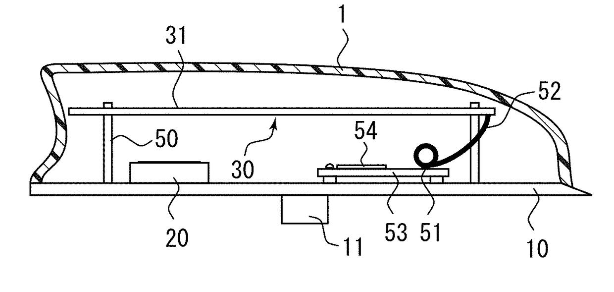
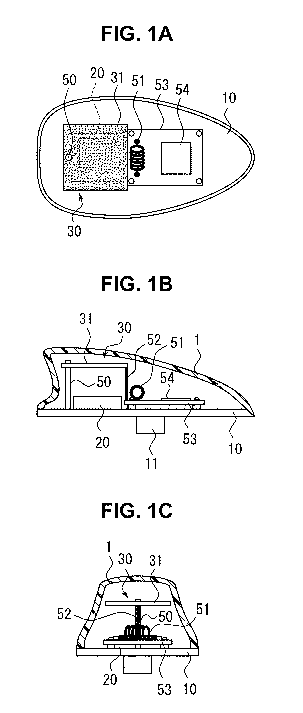
[0027]An embodiment for practicing the present invention will be described below with reference to the accompanying drawings. FIGS. 1A to 1C are partially cross-sectional schematic views, each explaining a composite antenna device according to the present invention. FIG. 1A is a plan view, FIG. 1B is a side view, and FIG. 1C is a front view. The composite antenna device according to the present invention can receive signals of a plurality of frequency bands for a vehicle and mainly includes a base plate 10, a first antenna 20, and a second antenna 30 as illustrated. The base plate 10, first antenna 20, and second antenna 30 are configured to be covered with an antenna cover 1. The antenna cover 1 has an inner space for housing an element or a circuit and defines an outer shape of the low-profile antenna device. The composite antenna device according to the present invention may be a composite antenna obtained by combining a capacitive antenna that can receive, e.g., signals of AM br...


PUM


Abstract

A composite antenna device is provided that is capable of achieving gain enhancement of a patch antenna and further miniaturization of the entire device size. A composite antenna device capable of receiving signals of a plurality of frequency bands for a vehicle includes a base plate, a first antenna, and a second antenna. The first antenna is constituted by a patch antenna placed on the base plate and capable of receiving signals of a first frequency band. The second antenna is constituted by a capacitive antenna capable of receiving signals of a second frequency band lower than the first frequency band. The second antenna includes a top load portion disposed so as to cover the first antenna and has at least one conductive planar body functioning also as a wave director for the first antenna.

Description

BACKGROUNDField of the Invention[0001]The present invention relates to a composite antenna device, and more particularly to a composite antenna device capable of receiving signals of a plurality of frequency bands for a vehicle.Description of the Related Art[0002]As vehicle antenna devices, those capable of receiving AM and FM broadcasts are generally used. There are available several types of the vehicle antenna device, such as a rod antenna, a film antenna, and a glass antenna. Recently, there is also available so-called a shark-fin antenna which is an antenna device with small size and low-profile. As to an antenna length, a rod antenna or the like is designed so as to have a length as ¼ wavelengths of an FM broadcast frequency band. Further, in the vehicle antenna device, since an antenna height, i.e., a length protruding from a vehicle roof is restricted by regulations for exterior fittings, there exists a helical antenna in which an antenna element is wound helically to reduce...

Claims


Application Information

Patent Timeline
IPC IPC(8): H01Q1/12H01Q5/30H01Q1/32H01Q21/06
CPCH01Q1/1214H01Q5/30H01Q1/3275H01Q21/065H01Q5/10H01Q5/40H01Q1/12H01Q1/36H01Q1/38H01Q1/42H01Q21/30H01Q1/521H01Q9/0428H01Q9/40H01Q19/22H01Q5/378H01Q1/32
Inventor IINO, SHINJI
Owner HARADA IND CO LTD
Why Eureka
Try Eureka