
Crossbow

a crossbow and crossbow technology, applied in the field of sports weapons, can solve the problems of increased demand for bow force, difficulty in design of crossbow, split bow string, etc., and achieve the effect of reducing rigidity, bow and crossbow weight, and reducing the dimensions and weight of an arrow

Inactive Publication Date: 2018-07-26
RASSULOV ALEKSEI MOSSUDOVICH
View PDF0 Cites 0 Cited by
  • Summary
  • Abstract
  • Description
  • Claims
  • Application Information

AI Technical Summary

Benefits of technology

The design of the slide and grooves in the stock of the crossbow allows the bow string to pass through and transmit its force to the arrow inside the stock. This reduces the size and weight of the bow and the amount of force needed to be applied to the bow string, which results in a lighter and more flexible crossbow. The use of helical grooves also eliminates friction between the slide and the rotation of the arrow, further reducing the weight and rigidity of the crossbow. The simplified crossbow design, which includes a structural element that connects parts of the crossbow, also contributes to the overall weight and simplification of the design.

Problems solved by technology

However, each of the said crossbows has an intricate and heavy moving unit dedicated for the spinning of an arrow or a bullet, hence requires increased demanded bow force, its weight and the weight of the crossbow on the whole.
The disadvantages of this crossbow are first of all comparatively large radial dimensions of an arrow which encloses a tubular stock and its enlarged length, required for interaction with annular slide and enabling sufficient duration of pins contact at the tailpiece of the arrow with the helical grooves of the stock.
Second of all, the necessity to make a split bow string complicates the design of the crossbow.

Method used


Image

  • Crossbow
  • Crossbow
  • Crossbow

Examples


Embodiment Construction

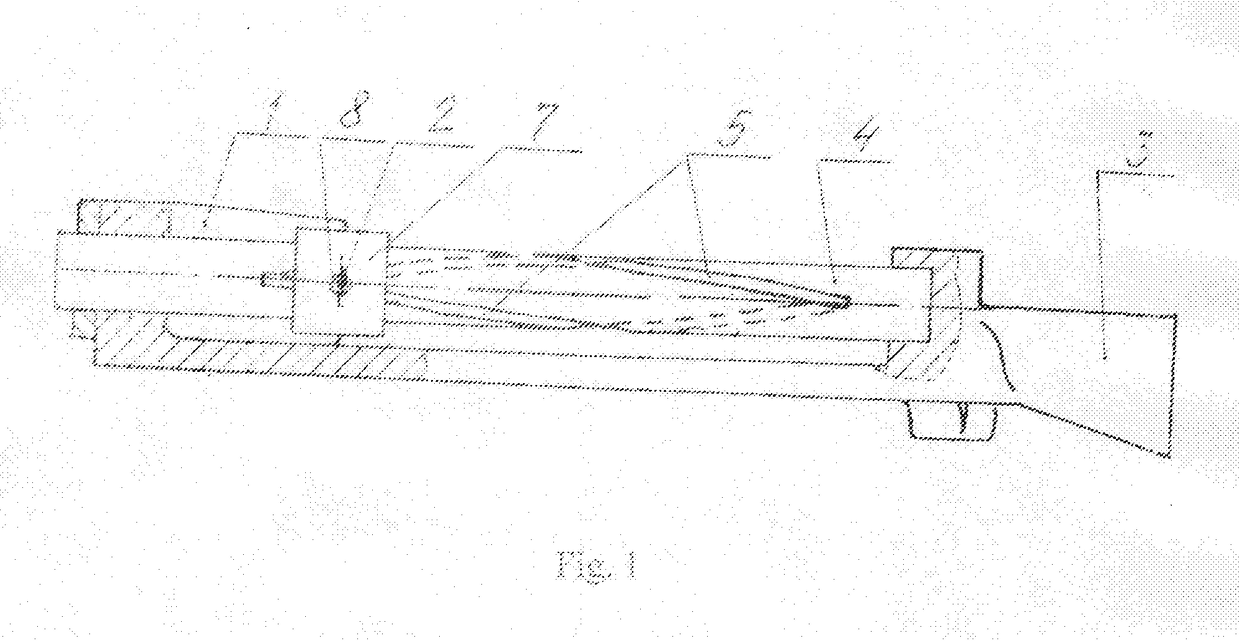
[0022]The crossbow contains a bow 1 with the bow string 2, a shoulder stock 3, a tubular stock 4 with longitudinal helical grooves of through design 5, an arrow 6, an annular slide 7.

[0023]In the annular slide 7 there are made radial openings 8 with inserted wearproof tube 9, that simultaneously goes through helical grooves 5 on the stock 4. The bow string 2 goes through the tube 9 and consequently crosswise the stock 4. The stock 4 is connected to the bow 1 and shoulder stock 3 by its nonsplit ends. In one of the crossbow design options the stock 4 is connected with the shoulder stock 3 and the bow 1 in such a way that the projection of the loose bow string 2 on the plane perpendicular to the longitudinal axis of the stock 4 is linear (FIG. 3), and the projection of the tensed bow string 2 on the same plane is S-shaped (FIG. 6).

[0024]Another possible option of crossbow design is a version where the stock 4 is connected to the shoulder stock 3 and the bow 1 in such a way that the pr...


PUM


Abstract

The invention relates to the field of sports weapons. The crossbow comprises a bow with a bow string, a shoulder stock and a tubular stock which connects said bow and shoulder stock and has two diametrically arranged longitudinal helical grooves, the helical grooves in the stock are of through design, and the bow string is passed through the helical grooves, wherein the helical grooves have a length of not less than the value of the bow string tensioning motion. Furthermore, an arrow to be launched is arranged inside the stock and is brought into engagement with the bow string such that an axial force and a rotational moment can be transmitted to one of the structural elements: by means of an annular slide with two radial openings which are open therein, are diametrically arranged and through which the bow string is passed, inside a tube inserted into said openings, or without a slide, only with the aid of a tube which is slipped onto the bow string, for which supports are formed on the bow string, or directly from the bow string, without a slide and without a tube. A simplification of the design, a reduction in the weight and necessary power of the crossbow, and an increase in the stabilization of an arrow during flight are achieved.

Description

CROSS-REFERENCE TO RELATED APPLICATIONS[0001]This application is a U.S. national stage application of an international application PCT / RU2016 / 000942 filed on 28 Dec. 2016, published as WO / 2017 / 116288, which international application claims priority of a Russian Federation patent application RU 2015157452 filed on 31 Dec. 2015.FIELD OF THE INVENTION[0002]The invention relates to the field of sports weapons and can be used for the creation of crossbows with increased power and accuracy providing minimum weight and design simplicity.BACKGROUND OF THE INVENTION[0003]There are known patents of the Russian Federation No 22059188 of 27 Apr. 1999, No 22150651 of 10 Jun. 2000, No 22239760 of 10 Nov. 2004, which provide torsion of the launched projectile (an arrow or a bullet) around the longitudinal axis for stabilization of an arrow during the flight. However, each of the said crossbows has an intricate and heavy moving unit dedicated for the spinning of an arrow or a bullet, hence requires...

Claims


Application Information

Patent Timeline
Patent Type & Authority Applications(United States)
IPC IPC(8): F41B5/12
CPCF41B5/12
Inventor RASSULOV, ALEKSEI MOSSUDOVICH
Owner RASSULOV ALEKSEI MOSSUDOVICH
Learn More