
High tolerance removable blind fastener

a blind fastener and high tolerance technology, applied in the direction of threaded fasteners, fastening means, dowels, etc., can solve the problems of limited tolerance (i.e. accuracy) of the outside diameter of the fastener, unacceptably low clamping load of the fastener for a narrow aperture,

Active Publication Date: 2018-07-26
KWIKBOLT
View PDF17 Cites 3 Cited by
  • Summary
  • Abstract
  • Description
  • Claims
  • Application Information

AI Technical Summary

Benefits of technology

This patent describes a removable blind fastener that can be used to clamp work-pieces with small apertures. The fastener includes an anti-rotation body and a hollow leg member with slots and resilient legs. A threaded tube and rod member are also included, which can be rotated to bring the legs into a clamping position. The legs are forced outward by the rod and are kept in a biased state. The threaded tube and legs are positioned at the opposite side of the anti-rotation body, allowing for independent adjustment of the thread diameter and maximum clamping load. The fastener can be easily operated with a rotating tool to clamp various work-pieces with small apertures.

Problems solved by technology

However, the tolerance (i.e. accuracy) of the outside diameter of the fastener is limited by the accuracy to which the thread on the screw member can be fabricated; typically this tolerance is and may even change over time as the threads are worn away through repeated actuation of the gripping member.
A further disadvantage of this arrangement is that the clamping load is limited by the diameter of the thread on the screw; therefore a fastener for a narrow aperture may have an unacceptably low clamping load because of the narrow thread.

Method used


Image

  • High tolerance removable blind fastener
  • High tolerance removable blind fastener
  • High tolerance removable blind fastener

Examples


Embodiment Construction

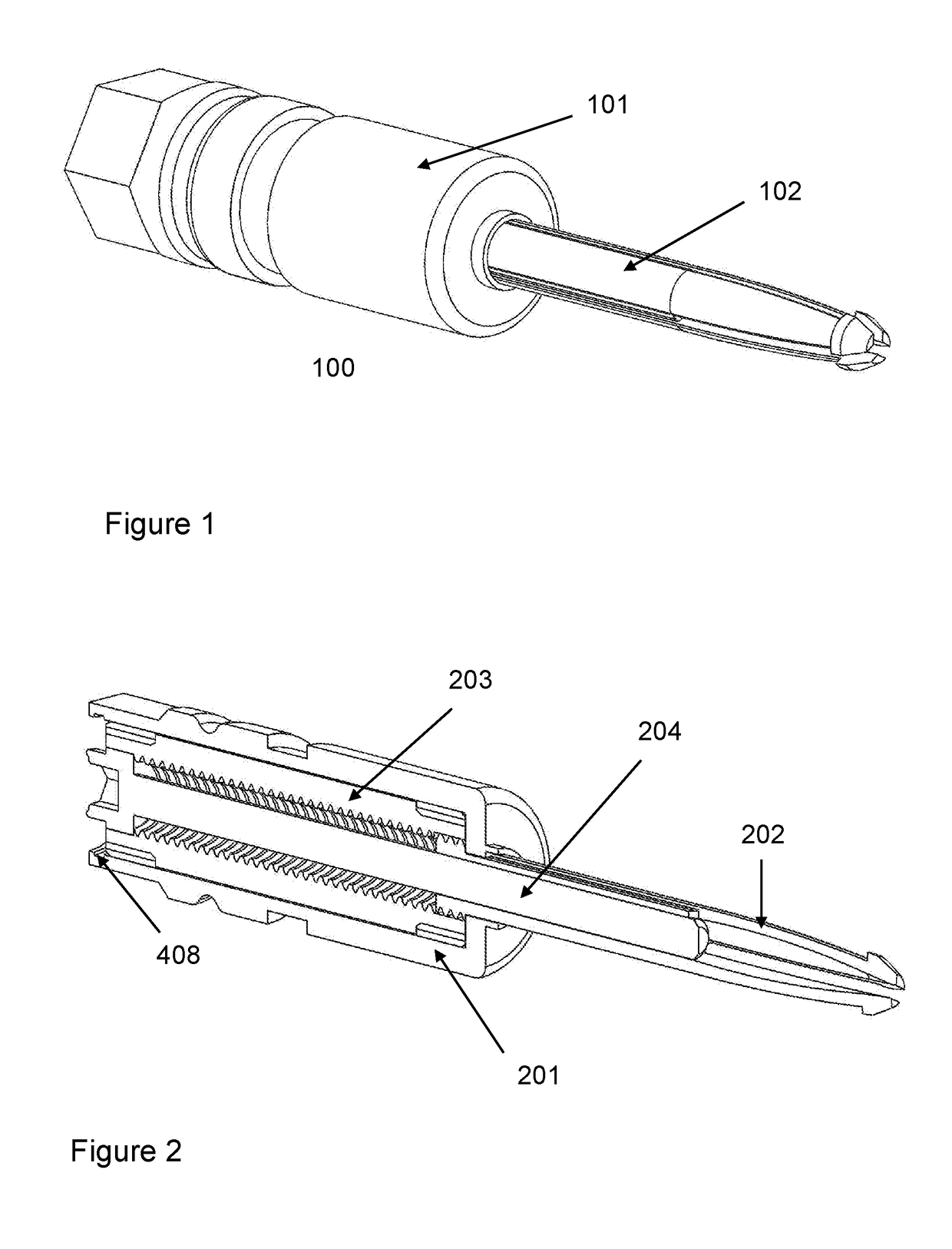
[0034]The present invention is a fastener 100 as shown in FIG. 1 for temporarily clamping two or more components together. A specific application for the fastener is for clamping parts of an airframe together while permanent fixings are installed; the fastener 100 can be removed and a permanent fixing installed in its place to complete the airframe. Many removable fasteners 100 may be used to temporarily clamp components of the airframe while permanent fixings are installed. The fastener 100 has a wide main body that remains proud of the surface of the parts, and a leg member for inserting into pre-drilled holes in the parts to be clamped. The fastener 100 is actuated by rotation of a part, causing the leg member to pull the parts together, as described in more detail below.

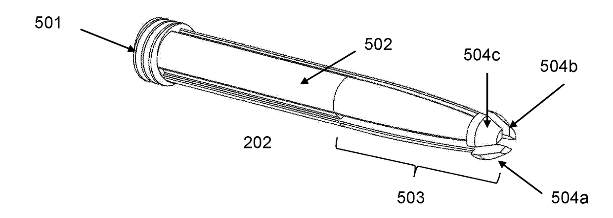
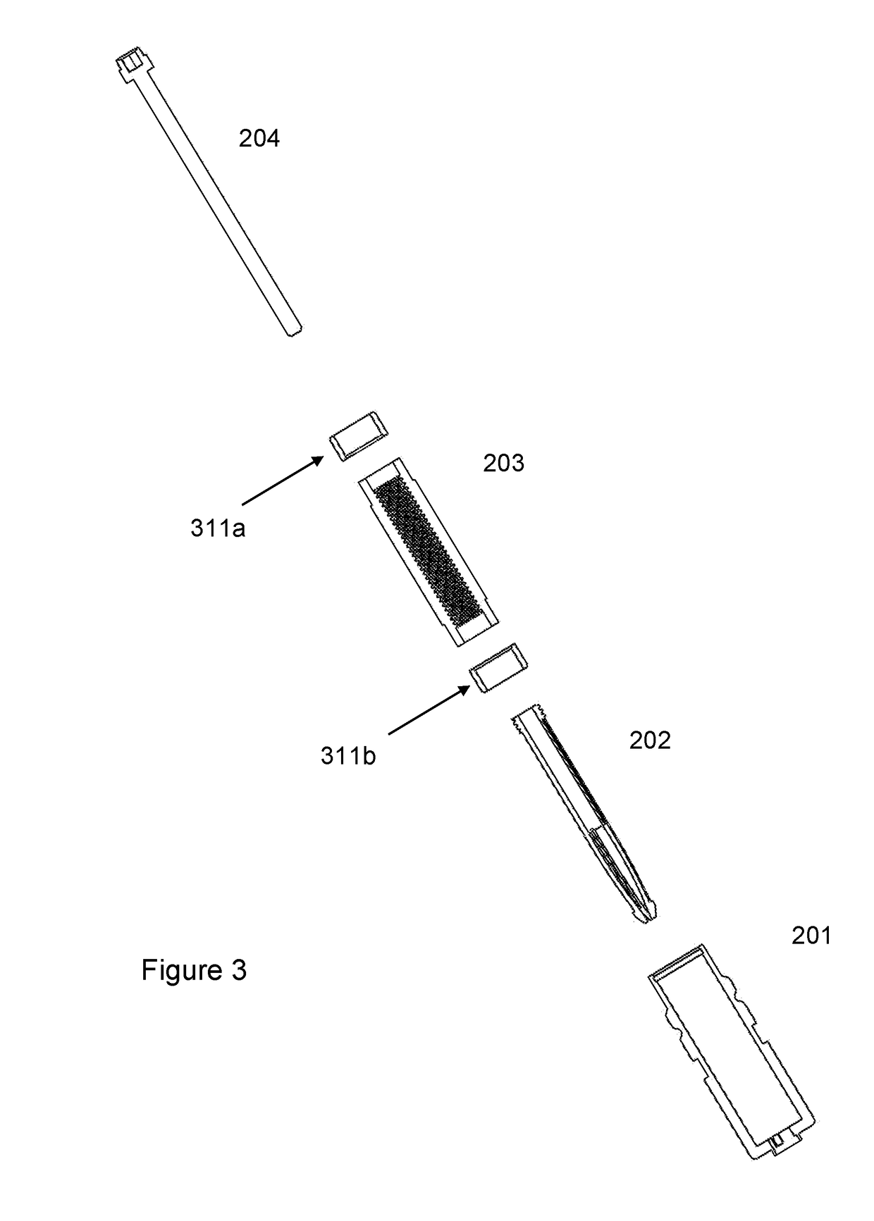
[0035]The fastener 100 has the following main components as shown in FIG. 2; a main body 201, a leg member 202, thread tube (also referred to as a threaded tube) 203 and rod 204.

[0036]The main body 201, shown in ...


PUM


Abstract

A removable blind fastener includes an anti-rotation body having an external face with an aperture, the external face being suitable for engaging with a surface of a work-piece to be clamped. The fastener further includes a hollow leg member with a plurality of slots defining outwardly biasable resilient legs at one end and an externally threaded portion at the other end, the leg member having a bore tapering towards the legs, the leg member being translatable through the aperture, the leg member and the aperture further having inter-engaging anti-rotation features to prevent the leg member from rotating about its central axis relative to the anti-rotation body. The fastener may further include a thread tube with an internal thread cooperable with the external thread of the leg member and located co-axially with the leg member and a rod member having a shaft with a head end and a free end.

Description

BACKGROUNDField of the Invention[0001]The present invention is concerned with improvements in or relating to removable blind fasteners and is particularly concerned with removable blind fasteners for use in temporarily co-joining wing elements of an aircraft frame.[0002]In the manufacture of aircraft frames, especially the wing elements, removable blind fasteners are used as a temporary fixing for the wing elements by inserting the fasteners in apertures provided in the wing elements. This is performed to determine the compatibility of the co-joined elements during an inspection process with adjustment of the apertures and alignment of the wing elements as necessary. After inspection and adjustment as required the removable blind fasteners are removed and permanent blind fasteners installed in the apertures.[0003]Aircraft structures, such as wing sections and fuselages, are assembled by fixing sheet materials to rigid members such as spars, ribs, runners, stringers etc. In order to ...

Claims


Application Information

Patent Timeline
IPC IPC(8): F16B19/10B25B31/00
CPCF16B19/109B25B31/005F16B13/0833
Inventor NIKLEWICZ, JAN
Owner KWIKBOLT
Learn More