Measurement apparatus and measurement method

a technology of measurement apparatus and measurement method, which is applied in the field of measuring biological information, can solve the problems of reducing the measurement accuracy of it is difficult to measure the pulse wave propagation velocity in daily life at all times, and achieves the effect of high accuracy

Inactive Publication Date: 2018-07-26
SEIKO EPSON CORP
View PDF3 Cites 0 Cited by
  • Summary
  • Abstract
  • Description
  • Claims
  • Application Information

AI Technical Summary

Benefits of technology

The invention relates to a pressing force measuring apparatus and a method for measuring an index relating to pulse wave propagation. The technical effects of the invention include accurately measuring the index even in cases where the two points for detecting pulse waves are close to each other. The pressing force by the first pressing portion is adjusted to induce high accuracy in the measurement. The index measured is the blood pressure, which is a familiar measurement for a large number of subjects. The measurement method involves detecting pulse waves at two different parts of the body and measuring the index relating to pulse wave propagation based on the pulse waves at the first and second parts. Even in cases where the two parts are close to each other, the technical effect ensures high accuracy in the measurement.

Problems solved by technology

In the technique of JP-A-2008-18035, it is necessary to attach a cuff to each of the upper limb and the lower limb of the living body, so it is difficult to measure the pulse wave propagation velocity in daily life at all times, for example.
However, as the two points for detecting the pulse waves are closer to each other, for example, the influence of the pressure at which the cuff presses each point relatively increases, and as a result, there is a problem that the measurement accuracy of the pulse wave propagation velocity decreases.

Method used


Image

  • Measurement apparatus and measurement method
  • Measurement apparatus and measurement method
  • Measurement apparatus and measurement method

Examples


first embodiment

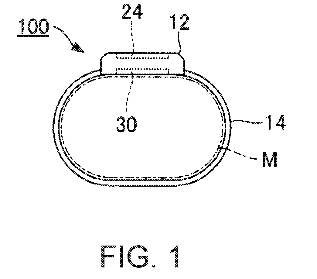
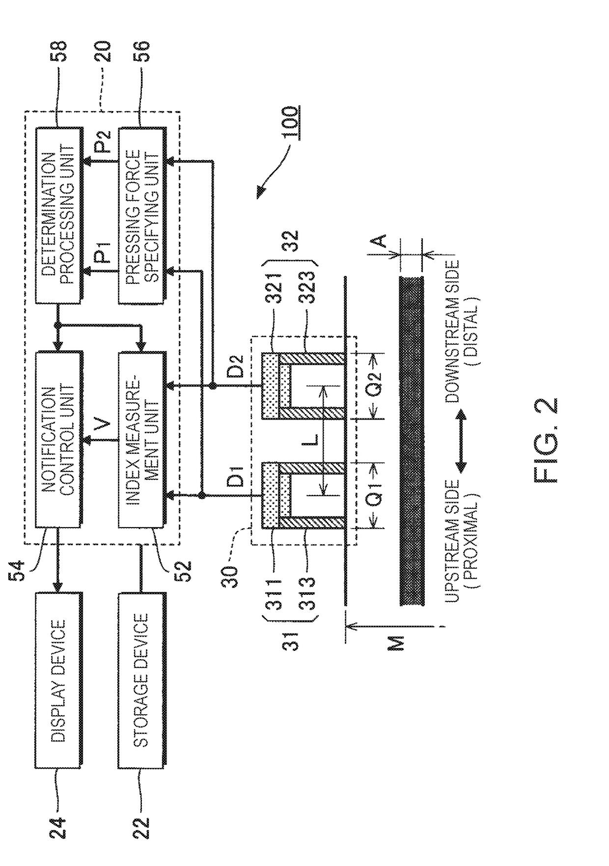
[0028]FIG. 1 is a configuration diagram of a measurement apparatus 100 according to a first embodiment of the invention. The measurement apparatus 100 of the first embodiment is a living body measurement device that non-invasively measures the biological information of a subject (an example of a living body), and is worn on a site to be measured (hereinafter referred to as “measurement part”) of the subject's body. As illustrated in FIG. 1, the measurement apparatus 100 of the first embodiment is a wristwatch-type portable device having a housing portion 12 and a belt 14, and is worn on the subject's body by winding the belt 14 of a band shape on a wrist (or a forearm) which is an example of the measurement part M. In the first embodiment, the pulse wave propagation velocity (PWV: Pulse Wave Velocity) is exemplified as biological information. The pulse wave propagation velocity is a velocity at which the pulse wave generated by the beat of the heart propagates in the artery, and is ...

second embodiment

[0059]A second embodiment of the invention will be described. In each of the following examples, the same reference numerals used in the description of the first embodiment are used for the elements whose actions or functions are the same as those of the first embodiment, and the detailed explanation thereof is appropriately omitted.

[0060]FIG. 12 is a configuration diagram of a detection device 30 of a second embodiment. As illustrated in FIG. 12, the detection device 30 of the second embodiment includes a first driving unit 315 and a second driving unit 325, in addition to the same first pulse wave detection unit 31 and the same second pulse wave detection unit 32 as those in the first embodiment. The first driving unit 315 displaces the first pressing portion 313 of the first pulse wave detection unit 31 under the control of the controller 20. The second driving unit 325 displaces the second pressing portion 323 of the second pulse wave detection unit 32 under the control of the c...

third embodiment

[0064]In the first embodiment and the second embodiment, a configuration for measuring the pulse wave propagation velocity V is exemplified. In the third embodiment, the blood pressure of the subject is estimated. Note that the same configuration as the first embodiment or the second embodiment is adopted for specifying and adjusting the pressing force P1 and the pressing force P2.

[0065]The index measurement unit 52 of the third embodiment measures the pulse wave propagation velocity V from the first detection signal D1 and the second detection signal D2, and estimates the blood pressure (at least one of systolic blood pressure and diastolic blood pressure) of the subject from the pulse wave propagation velocity V, by the same method as the first embodiment or the second embodiment. Specifically, the index measurement unit 52 calculates the blood pressure, by applying the pulse wave propagation velocity V to the expression expressing the correlation between the numerical value of th...


PUM


Abstract

A measurement apparatus includes a first pulse wave detection unit that detects a pulse wave at a first part pressed by a first pressing portion; a second pulse wave detection unit that detects the pulse wave at a second part pressed by a second pressing portion, the second part being located in a direction in which a traveling wave of the pulse wave travels from the first part; and an index measurement unit that measures an index relating to pulse wave propagation according to the pulse wave detected by the first pulse wave detection unit and the pulse wave detected by the second pulse wave detection unit, in which a pressing force first pressing portion exceeds a pressing force by the second pressing portion.

Description

BACKGROUND1. Technical Field[0001]The present invention relates to a technique for measuring biological information indicating a state of a living body.2. Related Art[0002]Various measurement techniques for measuring biological information such as a pulse wave propagation velocity have been proposed in the related art. For example, JP-A-2008-18035 discloses a measurement apparatus that measures a pulse wave propagation velocity by using a cuff attached to each of an upper limb and a lower limb of a living body. Specifically, the pulse wave propagation velocity of the living body is calculated using a time difference between the pulse wave detected by the cuff on the upper limb side and the pulse wave detected by the cuff on the lower limb side.[0003]In the technique of JP-A-2008-18035, it is necessary to attach a cuff to each of the upper limb and the lower limb of the living body, so it is difficult to measure the pulse wave propagation velocity in daily life at all times, for exam...

Claims


Application Information

Patent Timeline
IPC IPC(8): A61B5/022A61B5/021
CPCA61B5/022A61B5/02125A61B5/02141A61B5/02A61B5/681A61B5/6843
Inventor ENARI, MEGUMI
Owner SEIKO EPSON CORP
Why Eureka
Try Eureka