Damless hydroelectric power plant

Inactive Publication Date: 2018-07-19
KRIVCHIKOV VIKTOR IVANOVICH +1
View PDF0 Cites 0 Cited by
  • Summary
  • Abstract
  • Description
  • Claims
  • Application Information

AI Technical Summary

Benefits of technology

This patent describes a new way to design a hydraulic power plant that uses a bladed wheel and a chain transmission to generate electricity. The design helps prevent distortion of the bladed wheel and reduces material consumption. The housing structure is reinforced with tension members to correct any unevenness in the inner rim when mounting the power plant. The use of a rotation multiplier helps reduce resistance to rotation of the latest high-speed stage. Overall, this invention allows for the creation of large-scale, high-capacity hydraulic power plants.

Problems solved by technology

The main drawbacks of the technical solution are as follows.
The placement of a hydroelectric power plant in the bottom part of the flow of water, where particles of abrasive materials, such as bottom soil, are actively moving, negatively affects the functionality of the friction units, causing their premature wear.
The multi-stage kinematic multiplication scheme reduces the efficiency of the known hydroelectric power plant.
The main essential design drawback of this damless hydroelectric power plant for the use of high-capacity power unit as suggested consists in that the location of the chain drive for driving the driven shaft in accordance with the scheme given in the prior art does not ensure an even distribution of the power loads along the height of the bladed wheel, which can lead to its distortion and deformation of structural elements.
The second essential design drawback of this damless hydroelectric power plant is that the bladed wheel support rests on the only annular guide through the rollers with a horizontal rotation axis, which does not provide reliable resistance to displacement of the wheel towards the outer rim of the housing and leads to high pressure the guide is exposed to.
The third essential design drawback of this damless hydroelectric power plant is that its design does not provide reliable and uniform tight contact between the rollers with a vertical rotation axis and the cylinder surface.
The fourth essential design drawback of this damless hydroelectric power plant is that the use of only one cylinder of a large diameter and a large height in a large-scale hydroelectric power plant of a high unit capacity is economically unjustified in terms of manufacturing technology and unreasonable as a power unit structural element.

Method used


Image

  • Damless hydroelectric power plant
  • Damless hydroelectric power plant

Examples


Embodiment Construction

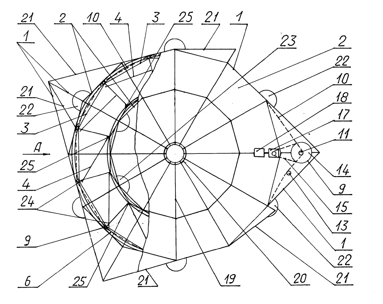
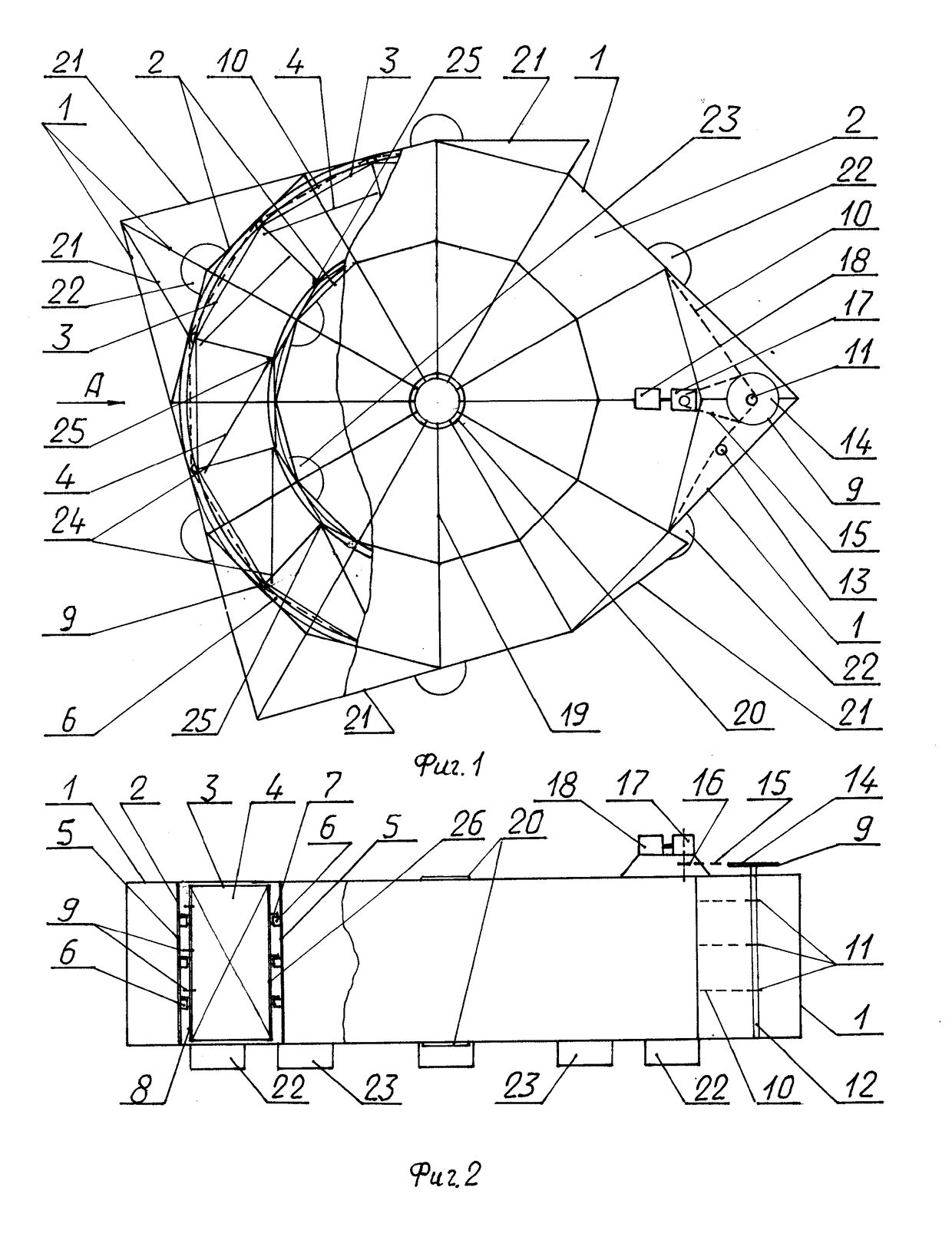
[0021]The provided damless hydroelectric power plant comprises a housing 1 with an annular part provided in the form of a tunnel 2 for receiving a bladed wheel 3 with rotary blades 4. On vertical struts 5 of the tunnel 2, annular support guides 6 are provided supporting the bladed wheel 3 by means of support rollers 7 with springs, having both horizontal and vertical rotation axes. On vertical struts 8 of the bladed wheel 3 outer rim, in the zone of the flow of water passing through the bladed wheel 3, gear sectors 9 are provided for pulling a step chain 10 of the first stage of the kinematic scheme for the torque transmission from the bladed wheel 3 to sprockets 11 provided on a shaft 12. The tension of the branches of the step chain 10 is controlled by a tensioning device 13. At the upper end of the shaft 12, there is a frame 14 with the gear sectors 9 that act as a large diameter drive sprocket of the second stage of the kinematic scheme for the torque transmission with the chain...


PUM


Abstract

A damless hydroelectric power plant can be used in installations for converting the kinetic energy of a gravity flow of water into electrical energy. A part of the housing of the hydroelectric power plant, in which the bladed wheel is placed, is in the form of an annular tunnel. Annular support guides on which the bladed wheel is supported are fixed in several rows on vertical struts of the tunnel inside the latter on both sides thereof. The annular tunnel structure is connected to a central bushing through tension members and to the containers, some of which contain a constant volume of air, while the others contain an adjustable volume of air. In each wheel sector, the bladed wheel comprises several rows of support rollers fixed on the vertical struts on the outside of the outer and inner wheel rims and having both horizontal and vertical rotation axes and provided with springs through which the wheel cooperates with the annular support guides of the tunnel, and gear sectors arranged in several rows fixed on the vertical struts of the outer wheel rim on each wheel sector and allowing for pulling the chains kinematically connected with a rotation multiplier and an electric power generator when rotating the bladed wheel.

Description

FIELD OF THE INVENTION[0001]The invention relates to hydropower industry, in particular to devices for converting kinetic energy of a gravity flow of water (river, sea and ocean currents) into electrical energy.BACKGROUND[0002]A known “Damless All-Season Hydroelectric Power Plant” by G. I. Ozerov comprises a horizontal bladed wheel with deployable blades, a vertical housing divided into cylinders and attached to a support in a rotating manner through the interaction between rollers and circular guides, connected with external rotary step-opening blades, whose rotation axes are shifted relative to each other at the same angle. A main and a standby electric power generators are attached to the support and connected to the housing and the gear wheel through mechanical transmission. The interior of the housing is provided with lattices, which are an extension of the external rotary blades, and with fixed internal blades formed of loosely fixed flaps resting on the lattice. The external ...

Claims


Application Information

Patent Timeline
IPC IPC(8): F03B17/06F03B7/00
CPCF03B17/063F03B7/00F05B2210/11Y02E10/28F03B13/10F03B17/06F05B2250/141F05B2260/4021Y02E10/20Y02E10/30
Inventor KRIVCHIKOV, VIKTOR IVANOVICHAKISHIN, DMYTRIY IVANOVICH
Owner KRIVCHIKOV VIKTOR IVANOVICH
Why Eureka
Try Eureka