Connection structure of plug-in power supply and light source plate

Active Publication Date: 2018-07-12
NINGBO YAMAO OPTOELECTRONICS CO LTD
View PDF1 Cites 0 Cited by
  • Summary
  • Abstract
  • Description
  • Claims
  • Application Information

AI Technical Summary

Benefits of technology

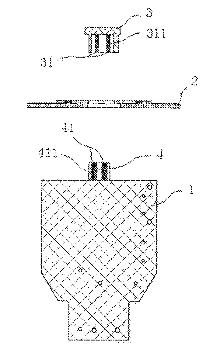
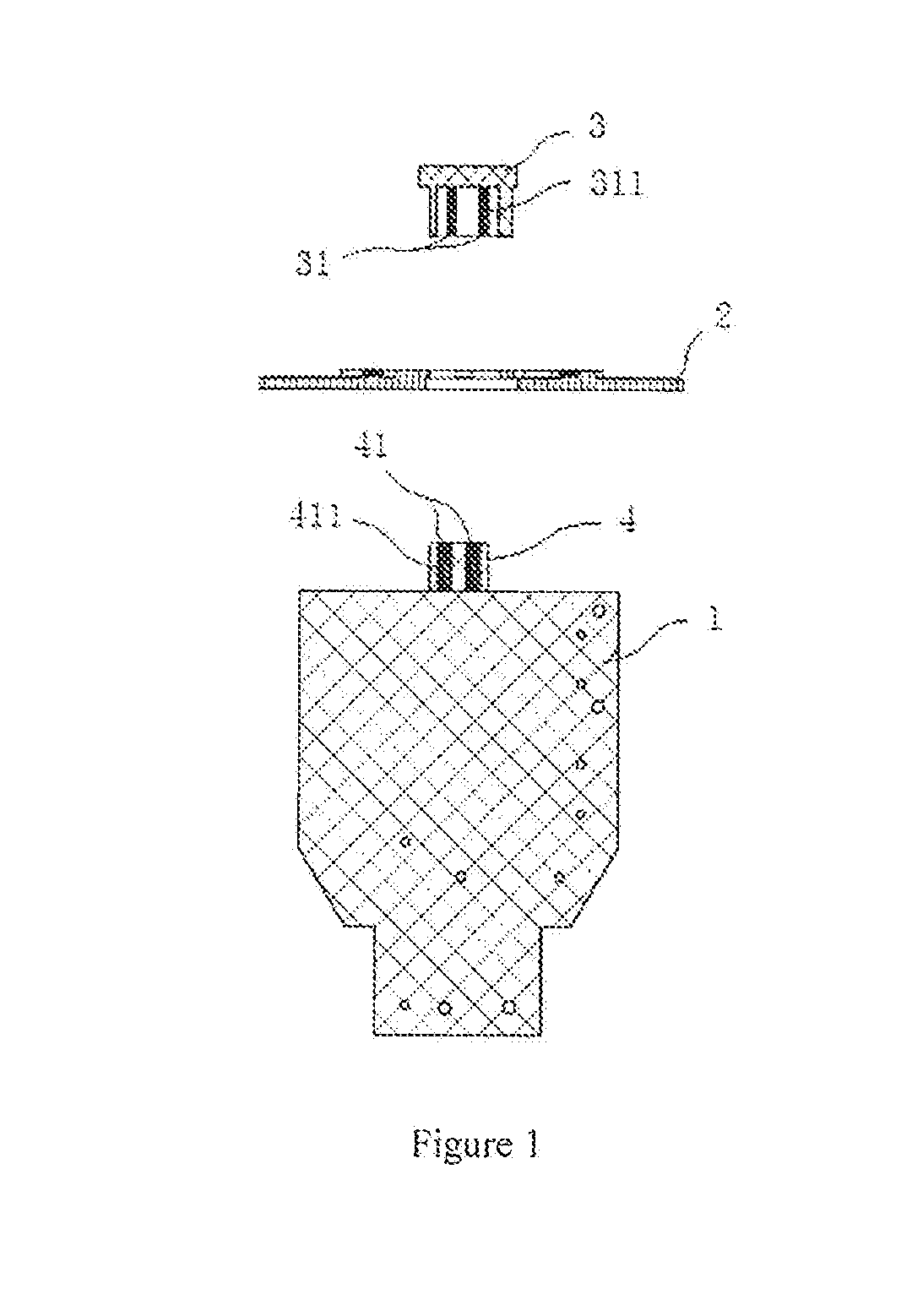
The present invention provides a connection structure between a plug-in power supply and a light source plate using a matching connection between a card on the power supply and a card slot on the light source plate. This connection method simplifies the process, improves reliability and security, and facilitates automatic and semi-automatic production, as well as large-scale production. The elastic piece arranged between the output point on the card and the soldering tin facilitates disassembly and assembly, and reduces costs. The metal contacts in the card slot and the metal brackets outside the card slot ensure the stability of the connection, and a length of fuse is arranged on the elastic piece to avoid safety accidents.

Problems solved by technology

The soldering process is manual soldering, and the manual soldering is difficult to control the amount of solder.
If the soldering is too much, it may cause short-circuit between electronic devices; if the soldering is too little, it may cause the problems such as desoldering, bubbles and pinholes etc.
The manual soldering is also likely to cause false soldering, pseudo soldering and so on, which may cause the circuit barrier, and affect the quality and safety of products.
Furthermore, manual soldering process is difficult to adapt to the demands of automation and semi-automation production, it limits the automation and semi-automation production, and results in low production efficiency.
In summary, the present method of connection of LED lights has the problems of the poor soldering quality of product, low production efficiency and low safety.

Method used


Image

  • Connection structure of plug-in power supply and light source plate
  • Connection structure of plug-in power supply and light source plate

Examples


Embodiment Construction

[0022]The present invention will now be described more fully hereinafter with reference to the accompanying drawings, in which exemplary embodiments of the invention are show 1. This invention may however, be embodied in many different forms and should not be construed as limited to the embodiments set forth herein. Rather, these embodiments are provided so that this disclosure will be thorough and complete, and will fully convey the scope of the invention to those skilled in the art. Like reference numerals refer to like elements throughout.

[0023]The terminology used herein is for the purpose of describing particular embodiments only and is not intended to be limiting of the invention. As used herein, the singular forms “a”, “an” and “the” are intended to include the plural forms as well, unless the context clearly indicates otherwise. It will be further understood that the terms “comprises” and / or “comprising,” or “includes” and / or “including” or “has” and / or “having” when, used h...


PUM


Abstract

The present invention provides a connection structure of a plug-in power supply and a light source plate, and it relates to the field of electronic circuit connection. The connection structure of the plug-in power supply, and the light source plate comprises: a card slot, which is soldered on the light source plate; a card, which is matched with the card slot and soldered on the power supply; metal contacts, which is arranged in the card slot; pre-printed circuits connected to the metal contacts and arranged on the card; the power supply is connected to the light source plate through the matching of the card slot and the card, which facilitates the disassembly and assembly and improves the production efficiency.

Description

CROSS-REFERENCE TO RELATED APPLICATIONS[0001]The present application claims priority to and the benefit of Chinese Patent Application No. CN 201710014908.1, filed on Jan. 9, 2017, the entire content of which is incorporated herein by reference.BACKGROUND OF THE INVENTION1. Field of the Invention[0002]The invention relates to the field of electronic circuit connection, more specifically, to a connection structure of a plug-in power supply and a light source plate.2. Description of the Related Art[0003]With the development of science and technology and the popularity of electricity, electronic products play an increasingly important role in people's lives, and facilitate people's lives. Therefore, the studies of electronic products have become the focus.[0004]LED (Light Emitting Diode) light, as one kind of light in the electronic products, has the advantages of long life, high brightness, short response time and high security, which lead to the rapid popularization of LED lights. How...

Claims


Application Information

Patent Timeline
IPC IPC(8): H01R12/72H01R12/70H01R13/02
CPCH01R12/72H01R12/7088H01R13/02H01R13/68
Inventor XU, QILIFANG, HUZHOU, YINYONG
Owner NINGBO YAMAO OPTOELECTRONICS CO LTD
Why Eureka
Try Eureka