Cold Source Based Noise Figure Measurement Using S-Parameters and a Vector Signal Transceiver/Vector Signal Analyzer/Spectrum Analyzer

a noise figure and cold source technology, applied in the field of instruments, can solve the problems of uncertainty in the measurement type and achieve the effect of accurate measurement of the noise figure(s) for the rf du

Active Publication Date: 2018-07-05
NATIONAL INSTRUMENTS
View PDF3 Cites 4 Cited by
  • Summary
  • Abstract
  • Description
  • Claims
  • Application Information

AI Technical Summary

Benefits of technology

[0010]In present day systems, both vector signal analyzers (VSAs) and vector network analyzers (VNAs) may be used to measure noise figures. Noise figure measurements using a spectrum analyzer are typically performed using the Y-factor method, which is based on the Johnson-Nyquist noise of a resistor at two different known temperatures or the noise of a calibrated noise source. When using VNAs, a cold source with impedance tuner is employed to obtain the noise figure (NF) for any source impedance value. In contrast, various embodiments disclosed herein provide a system and method for reutilizing previously measured parameters in a system to derive the NF for a device under test (DUT). Accordingly, the S-parameters of a DUT (for example a low noise amplifier—LNA) may be measured using a VNA using a specified test sequence. Then, the previously measured S-parameters of the DUT and other signal path components may be reutiliz...

Problems solved by technology

While the various analyzers have proven versatile, making accurate measu...

Method used


Image

  • Cold Source Based Noise Figure Measurement Using S-Parameters and a Vector Signal Transceiver/Vector Signal Analyzer/Spectrum Analyzer
  • Cold Source Based Noise Figure Measurement Using S-Parameters and a Vector Signal Transceiver/Vector Signal Analyzer/Spectrum Analyzer
  • Cold Source Based Noise Figure Measurement Using S-Parameters and a Vector Signal Transceiver/Vector Signal Analyzer/Spectrum Analyzer

Examples


Embodiment Construction

[0027]It is noted that the various terms or designations for circuits / components and signals as they appear herein, for example in such expressions as “switching circuit”, “delay circuit”, “source signal”, “stimulus signal”, etc. are merely names or identifiers used to distinguish among the different circuits / components and / or between different signals, and these terms are not intended to connote any specific meaning, unless directly indicated otherwise.

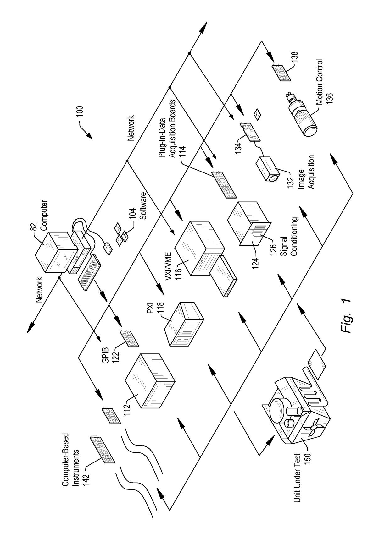
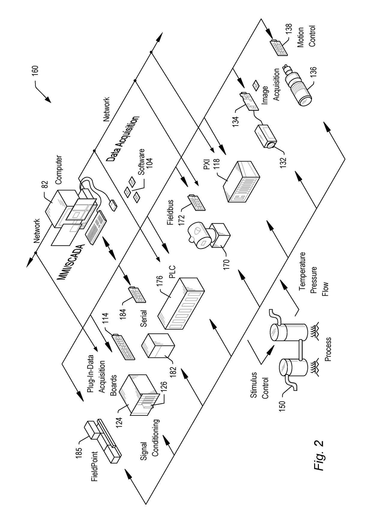
[0028]Embodiments of the present invention may be used in systems configured to perform test and / or measurement functions, to control and / or model instrumentation or industrial automation hardware, or to model and simulate functions, e.g., modeling or simulating a device or product being developed or tested, etc. More specifically, it may be used in various instances where noise figure measurements for one or more different radio frequency (RF) devices or RF devices under test may be required. However, it is noted that the present in...


PUM


Abstract

The noise figure for a radio frequency device may be obtained through power measurements. A signal flow graph based upon the S-parameter information of the entire RF system may be constructed. The S-parameter information may be representative of the microwave termination, the device, the measurement instrument and any losses due to additional components such as connecting cables/attenuators/switches, etc. The signal flow graph includes proper placement and values of the source nodes corresponding to each RF sub-system enumerated above. Noise figure measurements may include a calibration step and a measurement step. During the calibration step the noise figure and the noise temperature of the measurement instrument used for the measurement may be obtained. During the measurement step, the noise figure and the noise temperature of the device may be obtained based at least on the noise figure and noise temperature of the measurement instrument obtained during the calibration step.

Description

FIELD OF THE INVENTION[0001]The present invention relates to the field of instrumentation, and more particularly to performing noise figure measurements using analyzers.DESCRIPTION OF THE RELATED ART[0002]In many industrial applications (and others), instruments collect data or information from an environment or unit under test (UUT), and may also analyze and process acquired data. Some instruments provide test stimuli to a UUT. Examples of instruments include oscilloscopes, digital multimeters, pressure sensors, arbitrary waveform generators, digital waveform generators, etc. The information that may be collected by respective instruments includes information describing voltage, resistance, distance, velocity, pressure, oscillation frequency, humidity, and / or temperature, among others. Computer-based instrumentation systems typically include transducers for capturing a physical phenomenon and generating a representative electrical signal, signal conditioning logic to perform amplif...

Claims


Application Information

Patent Timeline
IPC IPC(8): G01R29/26G01R27/28
CPCG01R27/28G01R29/26
Inventor PAL, PRABHATVELKURU, VINAY KUMARAVENELL, BRIAN J.
Owner NATIONAL INSTRUMENTS
Why Eureka
Try Eureka