
Sensor unit for measuring a mass flow rate of a liquid hot-melt adhesive

a technology of liquid hot-melt adhesive and sensor unit, which is applied in the direction of indirect mass flowmeters, instruments, coatings, etc., can solve the problems of adversely affecting the application quality of hot-melt adhesive onto a substrate or workpiece, affecting the accuracy of obtained measurement results, and reducing the accuracy of measurement results, etc., to achieve good processability, reduce the effect of pressure loss within the system, and reduce the effect of pressure loss

Active Publication Date: 2018-06-21
NORDSON CORP
View PDF11 Cites 3 Cited by
  • Summary
  • Abstract
  • Description
  • Claims
  • Application Information

AI Technical Summary

Benefits of technology

The present invention provides a sensor unit for measuring the mass flow rate of a liquid hot-melt adhesive. The sensor unit avoids or reduces the disadvantages of previous designs, minimizes its impact on the fluid, is easy to make and position, and offers high measurement accuracy.

Problems solved by technology

A disadvantage of the described prior art has the effect that, due to their area, the sensors generate an additional flow resistance in the mass flow, which adversely affects the pump power required to generate a certain amount of hot-melt adhesive and leads to pressure losses within the system.
Moreover, the positioning of the sensors creates turbulences in the hot-melt adhesive which can result in uneven fluid exit particularly in the region near the dispensing nozzle, which adversely affects the application quality of hot-melt adhesive onto a substrate or workpiece.
In addition, due to the turbulences, accuracy restrictions with respect to the obtained measurement results are possible.
Furthermore, the sensors are not easy to maintain as a unit and not easily removable from the housing.

Method used


Image

  • Sensor unit for measuring a mass flow rate of a liquid hot-melt adhesive
  • Sensor unit for measuring a mass flow rate of a liquid hot-melt adhesive
  • Sensor unit for measuring a mass flow rate of a liquid hot-melt adhesive

Examples


Embodiment Construction

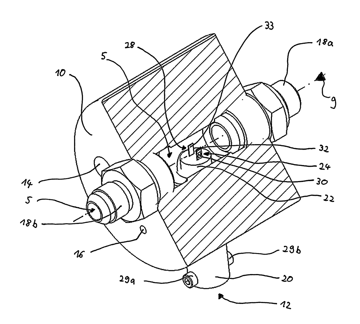
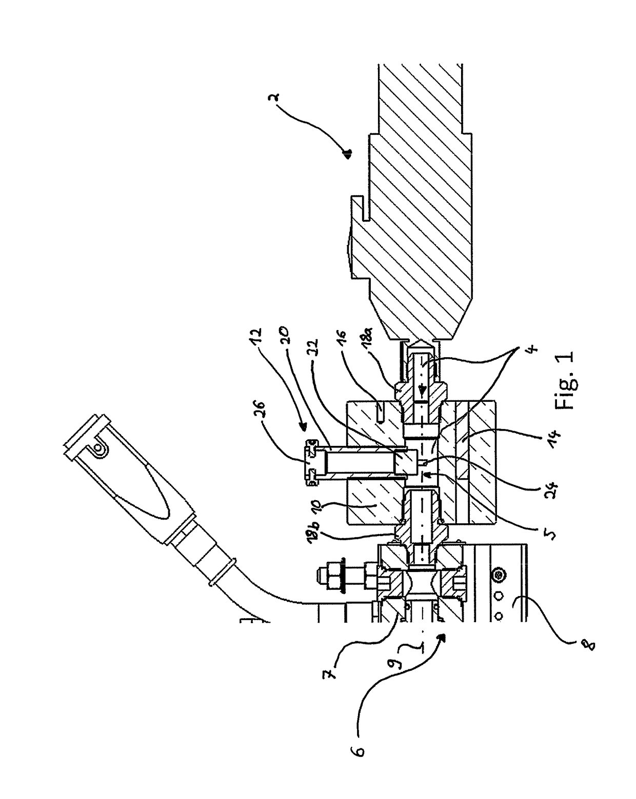
[0037]The system illustrated in FIGS. 1 and 2 in a first exemplary embodiment for applying hot-melt adhesive comprises a transport device 2, which transports melted hot-melt adhesive 4 (only indicated here) from a melter 76 (not shown in FIG. 1, see FIG. 11) to an application apparatus 6, a melter 76 (not shown here) (FIG. 11), an application apparatus 6 and a sensor unit 12 for measuring the mass flow rate of a liquid hot-melt adhesive.

[0038]The application apparatus 6 has a nozzle arrangement 8 which delivers the hot-melt adhesive 4 to a substrate or workpiece (not shown). The application apparatus 6 comprises, in a manner known per se a housing 7, flow channels formed therein, a valve arrangement and connections for introducing fluid, a control device for controlling the application apparatus and further components.

[0039]The sensor unit 12 is arranged in this exemplary embodiment between the application apparatus 6 and the transport device 2 and has a housing 10, which includes a...


PUM


Abstract

A sensor unit for measuring a mass flow rate of a liquid hot-melt adhesive is disclosed. The sensor unit includes a flow channel for the hot-melt adhesive, a first temperature measurement device positioned at a first position in the flow channel, a second temperature measurement device positioned at a second position in the flow channel and a heating device assigned to the second temperature measurement device, and a control unit for controlling the heating device and for measuring the mass flow rate. The controller is configured to adjust the temperature of the heating device assigned to the second temperature measurement device to a value, to determine the heating power for heating the heating device assigned to the second temperature measurement device, and to calculate the mass flow rate in the flow channel. The first and second temperature measurement devices are arranged substantially parallel to each other in the flow channel.

Description

CROSS-REFERENCE TO RELATED APPLICATIONS[0001]This application claims priority to German Patent Application No. DE 202016107242.5, filed Dec. 21, 2016, the disclosure of which is incorporated by reference in its entirety.FIELD OF THE INVENTION[0002]The present invention relates to a sensor unit for measuring a mass flow of a liquid hot-melt adhesive, comprising a flow channel for the hot-melt adhesive, a first temperature measurement device positioned at a first position in the flow channel for measuring a temperature of the hot-melt adhesive at the first position in the flow channel, a second temperature measurement device positioned at a second position in the flow channel and a heating device assigned to the second temperature measurement device for heating the second temperature measurement device, the second temperature measurement device being used for measuring a second temperature at the second, heated temperature measurement device, and a control unit for controlling the hea...

Claims


Application Information

Patent Timeline
Patent Type & Authority Applications(United States)
IPC IPC(8): G01F1/684G01F1/69B05C5/00B05C5/02
CPCG01F1/6847G01F1/69B05C5/001B05C5/0225G01F1/86B05C5/0254B05C11/1007G01F1/684G01F1/696
Inventor ROHRING, SVENMOHRDIECK, RALFLIPPELT, HELGEBORNKESSEL, ANDREAS
Owner NORDSON CORP
Learn More