
Gas detector

a gas detector and detector technology, applied in the direction of instruments, machines/engines, material electrochemical variables, etc., can solve the problems of inability to accurately represent difficulty in eliminating the influence of output current, etc., to achieve accurate detection of the concentration of sulfur oxides, rapid progress of sulfur oxidation reaction, and increase of the degree of output current change

Active Publication Date: 2018-05-31
TOYOTA JIDOSHA KK
View PDF1 Cites 1 Cited by
  • Summary
  • Abstract
  • Description
  • Claims
  • Application Information

AI Technical Summary

Benefits of technology

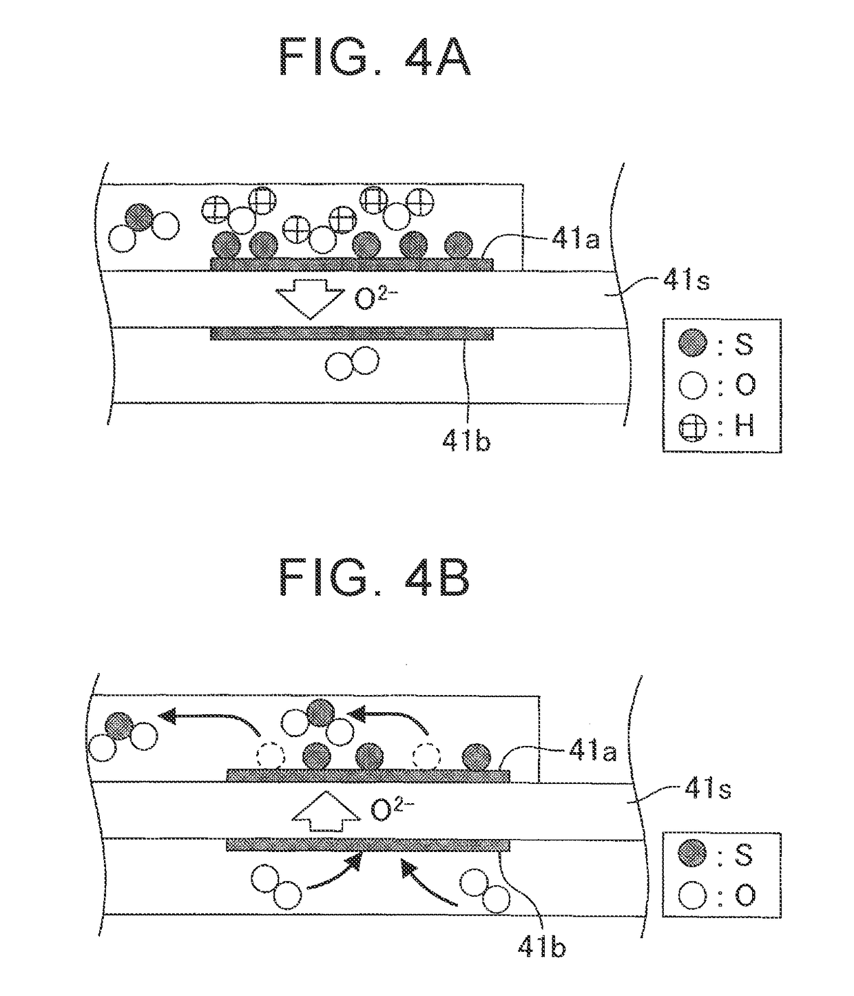
The patent describes a gas detector that can accurately detect the presence of sulfur oxides in exhaust gas. This is achieved by measuring the increase in oxide ions that move from one electrode to another when the engine air-fuel ratio becomes leaner. This results in an increase in output current. Overall, the gas detector provides a reliable and accurate way to detect the concentration of sulfur oxides in exhaust gas.

Problems solved by technology

For this reason, it is difficult to eliminate the influence on the output current resulted from the decomposition of water and to detect the output current only resulted from the decomposition of SOx components.
Accordingly, such a minimum value does not accurately represent the concentration of sulfur oxides.

Method used


Image

  • Gas detector
  • Gas detector
  • Gas detector

Examples


Embodiment Construction

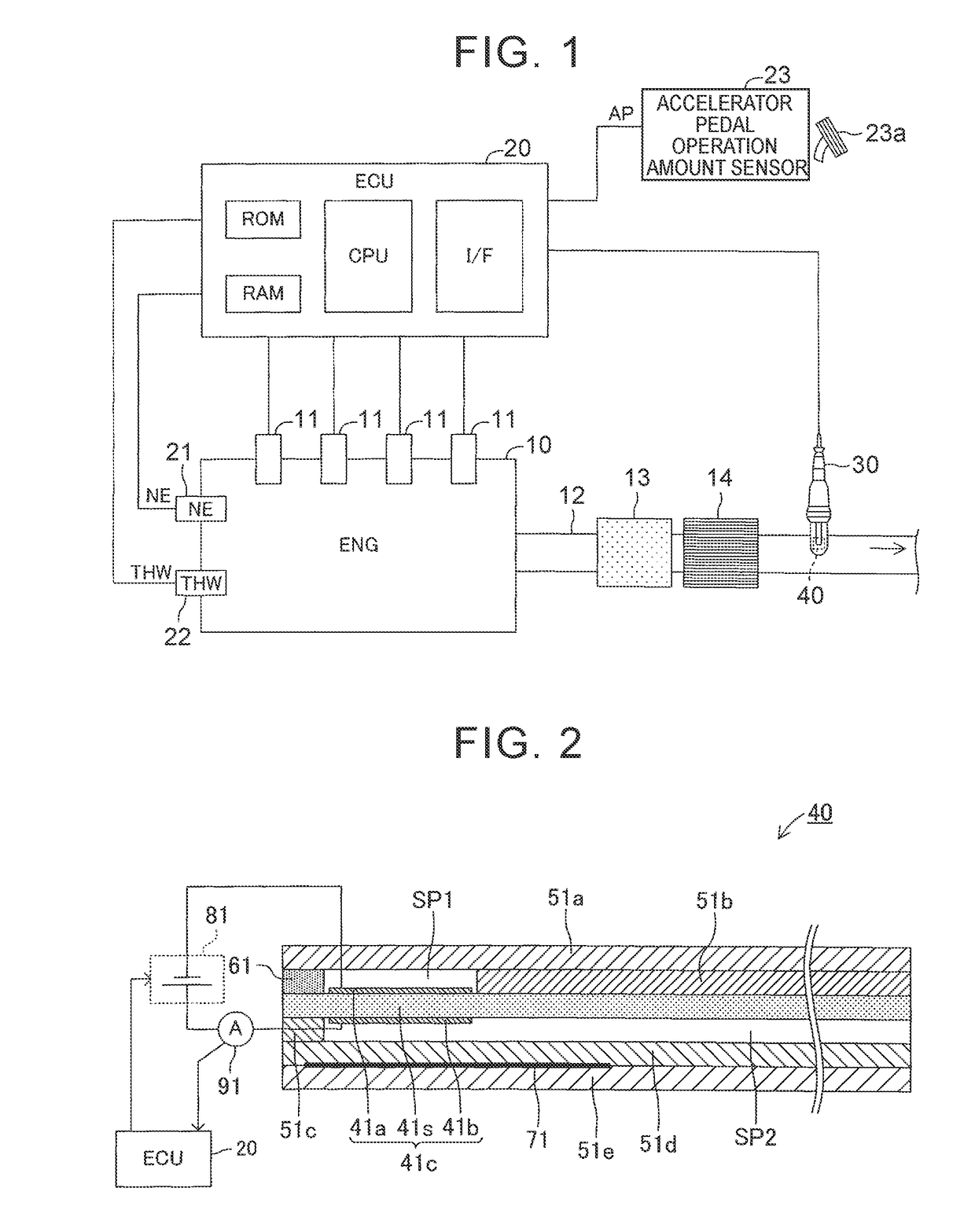
[0048]A description will hereinafter be made on a gas detector according to an embodiment of the disclosure with reference to the drawings. Note that the same or corresponding portions in all of the drawings of the embodiment are denoted by the same reference numerals.

[0049]A description will be made on the gas detector according to the embodiment of the disclosure. This gas detector is applied to a vehicle, which is not shown, and on which an “internal combustion engine 10 shown in FIG. 1” is mounted.

[0050]The internal combustion engine 10 is a well-known diesel engine. The internal combustion engine 10 includes a combustion chamber, which is not shown, and a fuel injection valve 11. The fuel injection valve 11 is disposed in a cylinder head section so as to be able to inject fuel into the combustion chamber. The fuel injection valve 11 directly injects the fuel into the combustion chamber in accordance with a command of an ECU 20, which will be described below. An exhaust pipe 12 ...


PUM

PropertyMeasurementUnit
applied voltageaaaaaaaaaa
voltageaaaaaaaaaa

Abstract

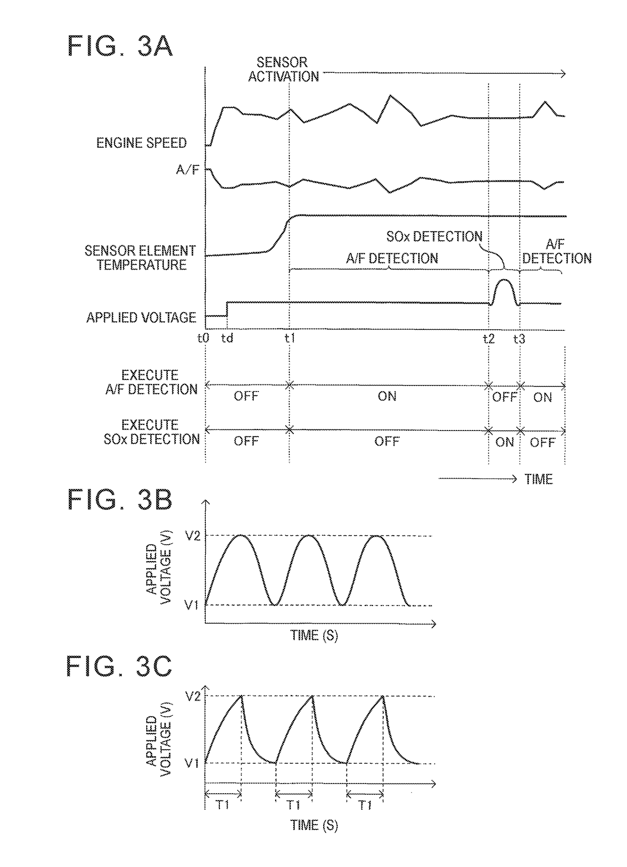
A gas detector includes a measurement control section that controls a voltage application section, obtains an output current flowing between a first electrode and a second electrode of an electrochemical cell, and detects a concentration of sulfur oxides in exhaust gas based on the output current. The measurement control section uses a minimum value of the output current obtained by using a current detection section in a period in which lowering sweep is executed and in which an applied voltage is a voltage within a detection voltage range that is equal to or lower than a decomposition initiation voltage of sulfur oxides as a parameter used for detection of the concentration of sulfur oxides.

Description

CROSS-REFERENCE TO RELATED APPLICATIONS[0001]This application claims priority to Japanese Patent Application No. 2016-233378 filed on Nov. 30, 2016, which is incorporated herein by reference in its entirety.BACKGROUND1. Technical Field[0002]The disclosure relates to a gas detector capable of determining presence or absence of sulfur oxides in a predetermined concentration or higher that are contained in exhaust gas (detected gas) of an internal combustion engine or detecting a concentration of sulfur oxides contained in the exhaust gas.2. Description of Related Art[0003]Conventionally, in order to control an internal combustion engine, an air-fuel ratio sensor (also referred to as an “A / F sensor”) that obtains an air-fuel ratio (A / F) of air mixture in a combustion chamber based on a concentration of oxygen (O2) contained in exhaust gas has widely been used. One type of such an air-fuel ratio sensor is a limiting current type gas sensor.[0004]Furthermore, a SOx concentration detector...

Claims


Application Information

Patent Timeline
Patent Type & Authority Applications(United States)
IPC IPC(8): G01N27/416G01N27/30
CPCG01N27/4162G01N27/304G01N27/4067G01N27/4072G01N27/4073G01N27/4075G01N27/409G01N27/41G01N27/48G01N27/419F01N2560/027G01N27/4065G01N27/407
Inventor WAKAO, KAZUHIROAOKI, KEIICHIROMATSUDA, KAZUHISA
Owner TOYOTA JIDOSHA KK
Learn More