
Distributed Control Synchronized Ring Network Architecture

a ring network and distributed control technology, applied in the field of improved, can solve the problems of affecting the operation of the network, and consuming a significant amount of power of the global clock tree, and achieves the effects of low latency on-chip communications, high operating frequency, and high bandwidth

Active Publication Date: 2018-05-24
DEGIRUM CORP
View PDF22 Cites 1 Cited by
  • Summary
  • Abstract
  • Description
  • Claims
  • Application Information

AI Technical Summary

Benefits of technology

The present invention provides a ring network architecture that simplifies the physical implementation of the network and allows for very high speed operation. The nodes of the ring network implement a source-synchronized clocking scheme, eliminating the need for an extensive low skew clock-tree across a large die area. No centralized controller is necessary, and the clocking and control schemes distributed among the nodes significantly simplify the network. Furthermore, the ring network architecture provides a powerful instrument for arbitration and synchronization, enabling each node to resolve the transaction messages from the other nodes in a precise order, even though the nodes are operating independently.

Problems solved by technology

As a result of these structures, the global clock tree consumes a significant amount of power.
Despite the above-described controls, clock skew may eventually degrade the performance of the global clock tree.
The variance of the physical distance among all the communication agents makes eliminating this clock skew difficult.

Method used


Image

  • Distributed Control Synchronized Ring Network Architecture
  • Distributed Control Synchronized Ring Network Architecture
  • Distributed Control Synchronized Ring Network Architecture

Examples


Embodiment Construction

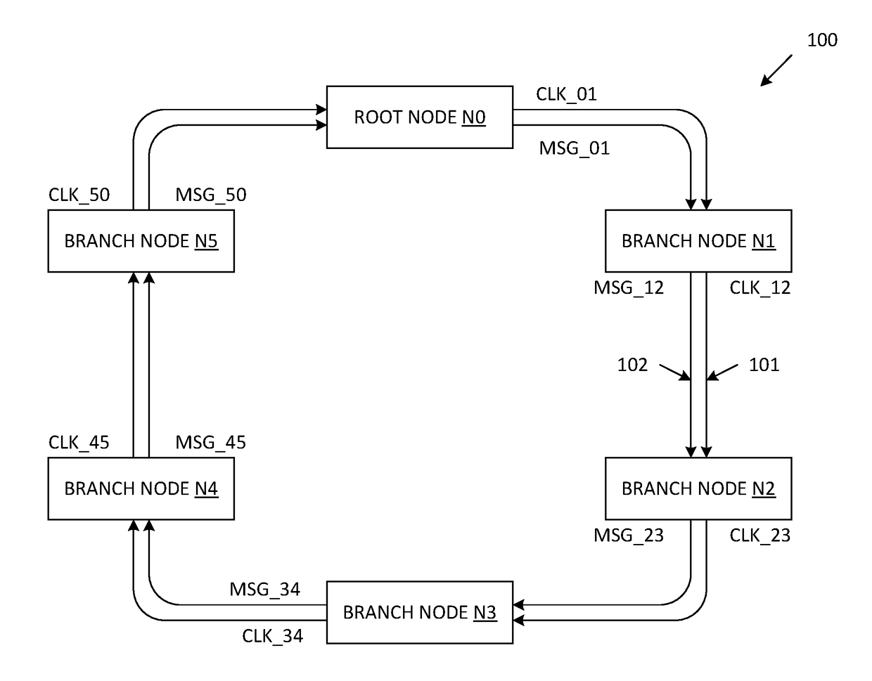
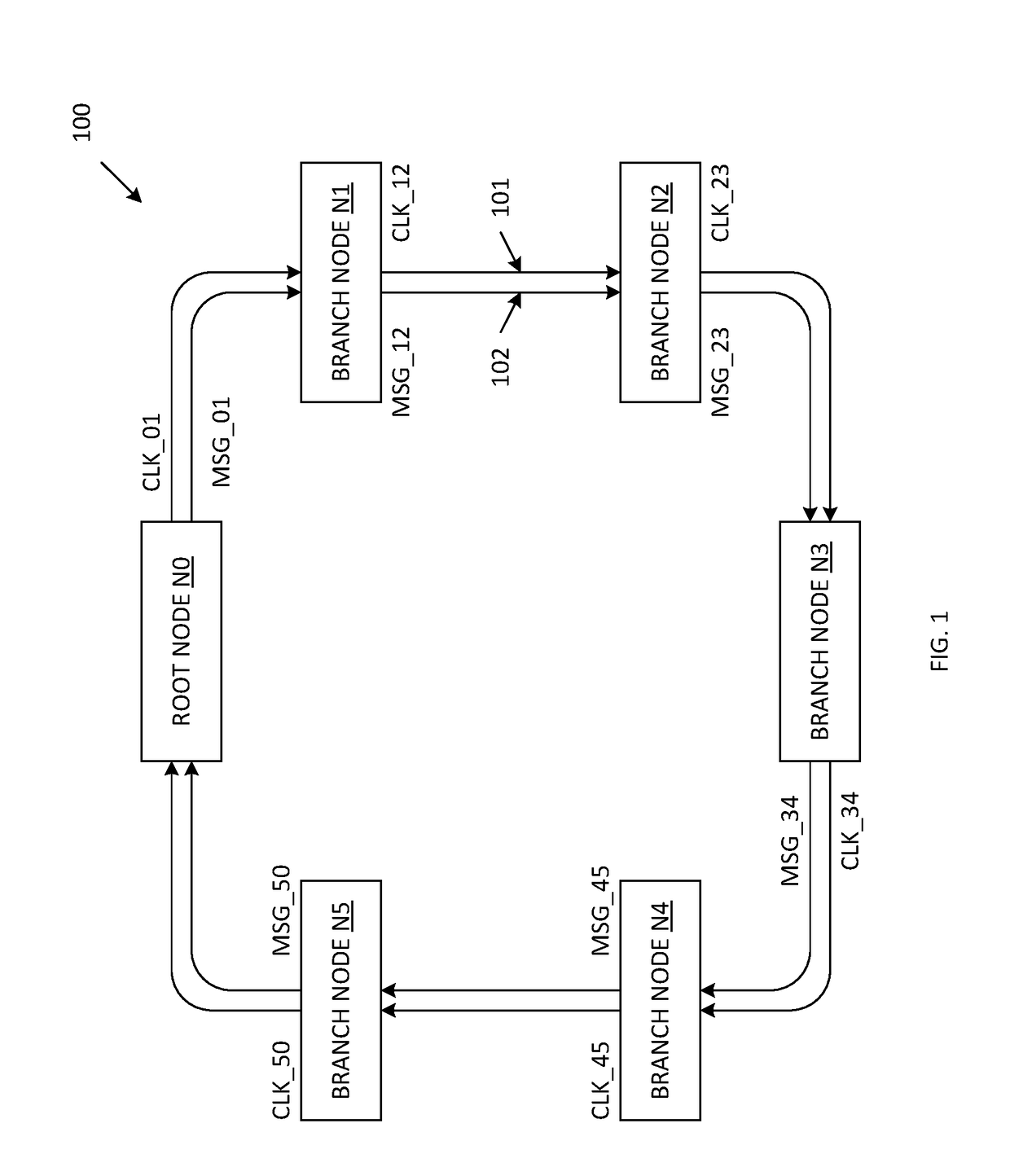
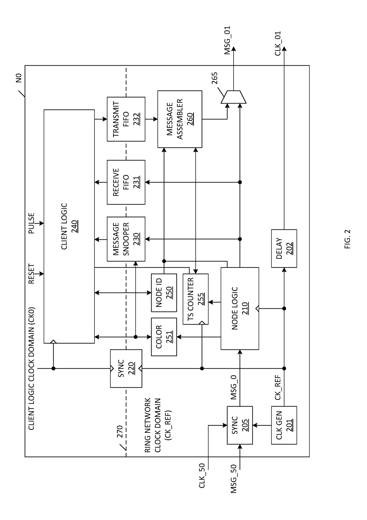
[0020]FIG. 1 is a block diagram of a distributed control synchronized ring network 100 in accordance with one embodiment of the present invention. Ring network 100 includes root node N0 and branch nodes N1-N5, which are connected in a ring. Although six communication nodes N0-N5 are included in the described examples, it is understood that other numbers of nodes can be included in other embodiments. However, each ring network will include one root node and one or more branch nodes. Each of the nodes N0-N5 receives a corresponding clock input signal and corresponding message input signals, and transmits a corresponding clock output signal and corresponding message output signals. The signals of the ring network 100 are unidirectional. In the illustrated embodiments, the signals of ring network 100 are routed in a clockwise manner (although this is not necessary). Each of the nodes N0-N5 has a transmitting neighbor and a receiving neighbor. For example, branch node N3 includes transmi...


PUM


Abstract

A ring network architecture includes multiple communication nodes configured in a ring. Wave pipelining is used to provide for high bandwidth and low latency on-chip communications. Each node implements a source-synchronized clocking scheme, such that there is no need to build an extensive low skew clock-tree across a large die area. A single reference clock signal is generated within a root node, and is routed through each of the nodes of the ring network in a unidirectional manner. Each node includes a timestamp counter and a color bit register, which store values that enable the node to resolve ordered transaction messages issued by the other nodes in a precise order, even though the nodes are operating independently, and receive the various transaction messages in totally different timing orders. Because the control logic is distributed among the nodes, no centralized controller is necessary.

Description

RELATED APPLICATIONS[0001]This application claims priority from U.S. Provisional Patent Application 62 / 425,792, entitled “Distributed Control Synchronized Ring Network Architecture”, which was filed on Nov. 23, 2016, and is incorporated by reference herein.FIELD OF THE INVENTION[0002]The present invention relates to an improved ring network architecture for achieving high bandwidth and low latency on-chip communications.RELATED ART[0003]A conventional semiconductor chip may include an extensive low-skew clock tree that distributes a global clock signal to each of a plurality of circuit blocks fabricated on the chip. The clock tree is designed to ensure that each of the plurality of circuit blocks receives the same input clock signal as each of the other circuit blocks. Implementing such a global clock tree requires extensive layout (die) area and a relatively complex interconnect structure (to enable point-to-point communication, broadcast communication, arbitration and synchronizat...

Claims


Application Information

Patent Timeline
IPC IPC(8): H04L12/42H04L7/04H04L7/00
CPCH04L12/422H04L7/04H04L7/0037H04J3/0638H04L7/0008H04L12/437H04L12/42G06F1/10G06F30/396
Inventor TAM, KIT S.
Owner DEGIRUM CORP
Learn More