
Integrated Gas Separation-Turbine CO2 Capture Processes

a gas separation and co2 capture technology, applied in the field of membrane-based membrane separation processes, can solve the problems of limited cooling, high cost of treating hot gas, and loss of a significant fraction of the heat required to drive the turbo expander, so as to reduce the environmental impact of the plant

Active Publication Date: 2018-05-17
MEMBRANE TECH & RES
View PDF0 Cites 2 Cited by
  • Summary
  • Abstract
  • Description
  • Claims
  • Application Information

AI Technical Summary

Benefits of technology

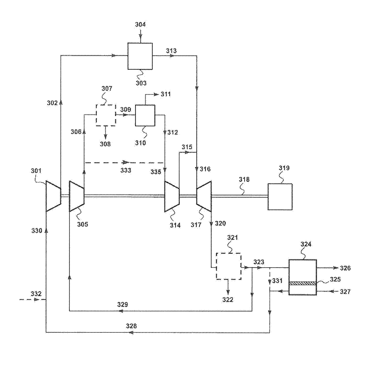
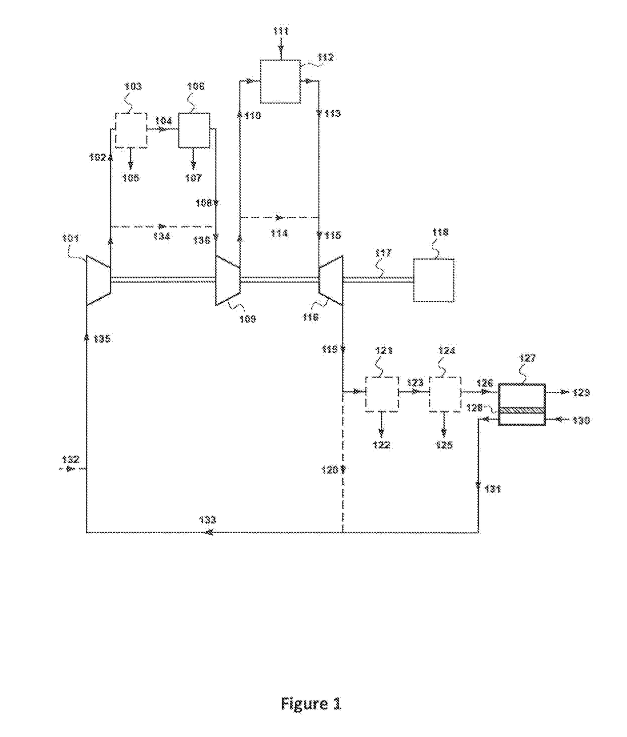
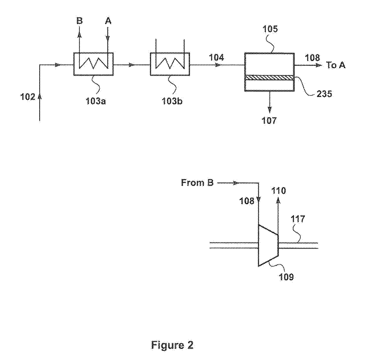
The patent text describes a process for capturing carbon dioxide from the exhaust gas of a power plant. By integrating the carbon capture step into the turbine compression process, energy and cost savings can be achieved. By positioning the carbon capture unit at an intermediate compression stage, the amount of cooling required is reduced, and the process is simplified. The residue stream produced by the process has a low carbon dioxide content, which greatly reduces the environmental impact of the plant.

Problems solved by technology

The carbon dioxide capture process could be performed on the compressed gas stream at 30 bar, as in conventional processes, but this gas is extremely hot, typically about 500 to 800° C. Cooling this gas to a temperature low enough for a conventional membrane or absorption or adsorption process that could treat this hot gas would be expensive and would lose a significant fraction of the heat required to drive the turbo expander.
This means only limited cooling would be required, thus considerably simplifying the process.

Method used


Image

  • Integrated Gas Separation-Turbine CO2 Capture Processes
  • Integrated Gas Separation-Turbine CO2 Capture Processes
  • Integrated Gas Separation-Turbine CO2 Capture Processes

Examples


example 1

lt Membranes Used for Gas Separation Step, Two Compressor Loops (not in Accordance with the Invention)

[0120]As a comparative example, a computer calculation was performed to model the performance of the process with the design shown in FIG. 4. Each compressor was assumed to deliver a compressed gas at 30 bara. The ratio of turbine exhaust gas directed to the sweep unit to gas directed to compression step 401b was set at 3:1. Molten salt membranes were assumed to be used for step 412. The permeate side of the membranes was assumed to be at 2 bara.

[0121]The results of the calculation are shown in Table 1.

TABLE 1Stream416428406445444419425413429Molar2230240111912352135725259flow(kmol / h)Temp381525253756342537411(° C.)Pressure30112301221(bara)Component (vol %)Oxygen020.7154.54.54.24.51.17.2Nitrogen1.677.362.169.668.863.670.08.690.3Carbon1.0020.423.524.321.423.590.30.8dioxideMethane93.100000000Water01.01.81.51.510.01.500.5Argon01.00.70.80.80.80.801.1Ethane3.200000000Prop0.700000000n-butan...


PUM

PropertyMeasurementUnit
pressureaaaaaaaaaa
temperatureaaaaaaaaaa
temperaturesaaaaaaaaaa

Abstract

Sweep-based gas separation processes for reducing carbon dioxide emissions from gas-fired power plants. The invention involves at least two compression steps, a combustion step, a carbon dioxide capture step, a power generate step, and a sweep-based membrane separation step. One of the compression steps is used to produce a low-pressure, low-temperature compressed stream that is sent for treatment in the carbon dioxide capture step, thereby avoiding the need to expend large amounts of energy to cool an otherwise hot compressed stream from a typical compressor that produces a high-pressure stream, usually at 20-30 bar or more.

Description

CROSS-REFERENCE TO RELATED APPLICATIONS[0001]This application is a divisional of U.S. application Ser. No. 15 / 353,310, filed on Nov. 16, 2016, the disclosure of which is hereby incorporated herein by reference in its entirety.FIELD OF THE INVENTION[0002]The invention relates to membrane-based gas separation processes, and specifically to sweep-based membrane separation processes to remove carbon dioxide from combustion gases. More particularly, the invention uses a low-pressure, low-temperature CO2 capture step integrated into gas-fired power plants.BACKGROUND OF THE INVENTION[0003]Presented below is background information on certain aspects of the present invention as they may relate to technical features referred to in the detailed description, but not necessarily described in detail. The discussion below should not be construed as an admission as to the relevance of the information to the claimed invention or the prior art effect of the material described.[0004]Much of the world'...

Claims


Application Information

Patent Timeline
Patent Type & Authority Applications(United States)
IPC IPC(8): B01D53/14H02K7/18F02C3/20F02C3/04B01D53/00B01D53/02B01D53/22F25J3/08
CPCF25J2205/80F25J2210/80F25J2210/50F25J2260/50F25J2220/50F05D2220/76F25J3/08H02K7/1823F02C3/20F02C3/04B01D53/005B01D53/02B01D53/229B01D53/1475Y02E20/16B01D53/002B01D53/22B01D53/265B01D53/62F02C3/00F02C6/00F02C6/18B01D2251/306B01D2251/606B01D2252/204B01D2256/22B01D2257/102B01D2257/104B01D2257/504B01D2257/80B01D2258/0283F05D2260/61Y02E20/18Y02A50/20Y02C20/40Y02E20/32
Inventor BAKER, RICHARD W.MERKEL, TIMOTHY C.
Owner MEMBRANE TECH & RES
Learn More