
Blood pressure measurement device with a MEMS pump and control method for the same

Inactive Publication Date: 2018-05-17
MICROLIFE CORP
View PDF3 Cites 3 Cited by
  • Summary
  • Abstract
  • Description
  • Claims
  • Application Information

AI Technical Summary

Benefits of technology

The present invention aims to overcome the problems of prior blood pressure measurement devices by controlling the voltage level of a MEMS pump to regulate the inflation speed of the device. This allows for a stable and safe application of pressure for accurate blood pressure readings. The invention also provides a way to maintain a stable air flow in the bladder, which is important for some applications.

Problems solved by technology

Therefore, a complicated control circuit is required, and a good effect is usually difficult to achieve.

Method used


Image

  • Blood pressure measurement device with a MEMS pump and control method for the same
  • Blood pressure measurement device with a MEMS pump and control method for the same
  • Blood pressure measurement device with a MEMS pump and control method for the same

Examples


Embodiment Construction

[0023]To make it easier for our examiner to understand the objective, technical characteristics, structure, innovative features, and performance of the invention, we use preferred embodiments together with the attached drawings for the detailed description of the invention. For simplicity and clarity, the drawings are provided for showing the overall structure of the invention, and the characteristics of the prior art and their corresponding detailed description is omitted to avoid unnecessarily blurring the claims of the the present invention. It is noteworthy that same numerals are used to represent the same elements in the drawings respectively.

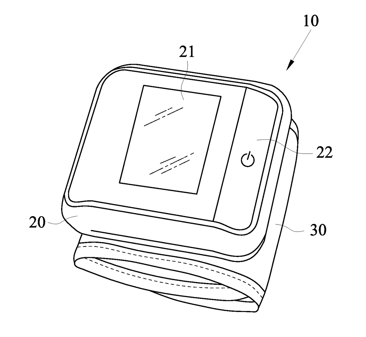
[0024]With reference to FIG. 1 for a perspective view of a blood pressure measurement device 10 in accordance with a preferred embodiment of the present invention, the blood pressure measurement device 10 of this preferred embodiment is a wrist sphygmomanometer. However, the invention is not limited to the wrist sphygmomanometer only, and ...


PUM


Abstract

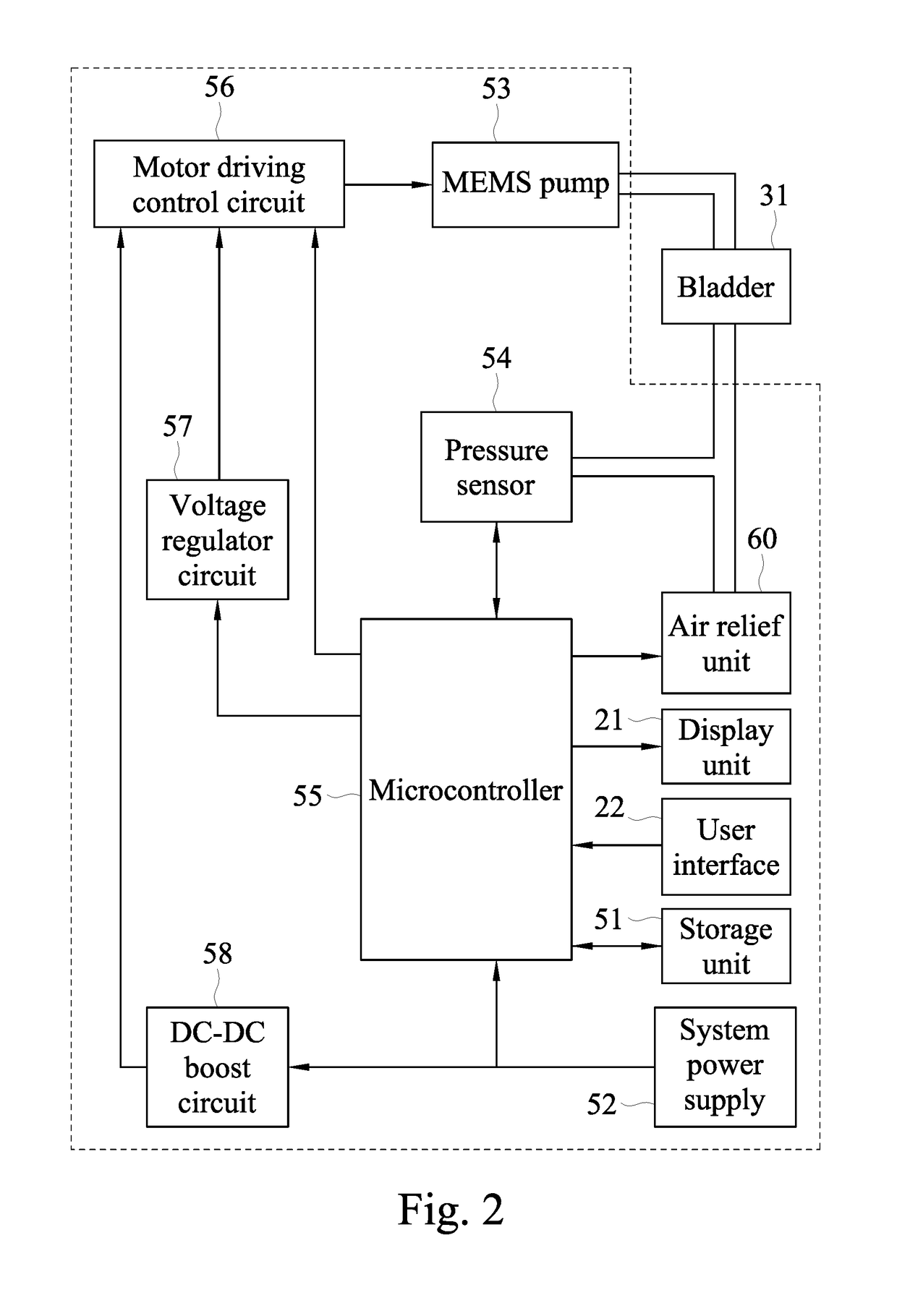
This invention discloses a blood pressure measurement device including a cuff having a bladder wrap around an object to be measured, a MEMS pump for inflating the bladder with air, a pressure sensor for monitoring the pressure in the bladder, and a microcontroller for controlling the pressure sensor to continuously receive pressure signals during the process of inflating the bladder, converting the pressure signals into blood pressure values, and controlling a drive voltage level of the MEMS pump to maintain an air inflation speed of the MEMS pump in a predetermined inflation speed range. The invention further discloses a method for controlling a fixed frequency change of the blood pressure measurement device.

Description

CROSS-REFERENCE TO RELATED APPLICATIONS[0001]This non-provisional application claims priority under 35 U.S.C. § 119(a) on Patent Application No(s). 105136775 filed in Taiwan, R.O.C. on Nov. 11, 2016, the entire contents of which are hereby incorporated by reference.FIELD OF INVENTION[0002]The present invention relates to a blood pressure measurement device, in particular, to a blood pressure measurement device with a MEMS pump. The present invention also relates to a control method of the blood pressure measurement device, in particular, to a control method for controlling the inflation speed of the MEMS pump in a predetermined range during the inflation process of the bladder.BACKGROUND OF INVENTION1. Description of the Related Art[0003]In general, there are mainly two ways for the conventional blood pressure measurement device to measure blood pressure: deflation type measurement, and inflation type measurement. In a deflation type blood pressure measurement process, a pump is pro...

Claims


Application Information

Patent Timeline
IPC IPC(8): A61B5/022
CPCA61B5/022A61B5/11A61M2205/3331F04B43/043A61B5/02141A61B5/02233A61B5/0225A61B2562/0247A61B2560/0214F04B19/006F04B35/04F04B45/047F04B49/065F04B49/08F04B49/20F04B2205/05A61B5/01A61B5/024A61B2562/028A61B5/742F04B17/003H10N30/802
Inventor LIN, CHIA-MING
Owner MICROLIFE CORP
Learn More