
Mr audio unit

a technology of audio unit and microphone, which is applied in the direction of sound producing device, magnetic variable regulation, sensors, etc., can solve the problems of patient frustration, patient unintentional movement, patient unease and stress,

Active Publication Date: 2018-04-26
SIEMENS HEALTHCARE GMBH
View PDF6 Cites 5 Cited by
  • Summary
  • Abstract
  • Description
  • Claims
  • Application Information

AI Technical Summary

Benefits of technology

The patent text describes a way to reduce noise produced by a magnetic resonance machine. A computer program is provided that can be executed by a control unit of an audio unit. This program can quickly, reliably, and robustly perform the required steps to effectively control the audio unit. The control unit, which may be a computer or a device with appropriate software, is specified to be able to perform the necessary functions efficiently. This way, the audio unit can be easily and quickly controlled to minimize noise and provide a better patient experience.

Problems solved by technology

This loud audible sound usually causes unease and stress in the patient during the MR measurement (e.g., during prolonged MR pulse sequences).
The result is often frustration of the patient and unintentional movements of the patient (e.g., which may reduce the image quality).
The opportunities for reducing noise using passive methods are rather limited.
Although passive methods are normally sufficient for lowering the sound pressure to a level that does not damage the hearing organ of the patient, passive methods are not adequate for preventing the associated unpleasantness for the patient during the MR measurement.
Active methods may supplement passive methods by using destructive interference to attenuate the audible sound further.
This method may suffer from interference to the acoustic field and signal delays as a result of the long acoustic path.
For high-frequency noise components, especially components above 1 kHz, interference and signal delays may not be eliminated effectively.
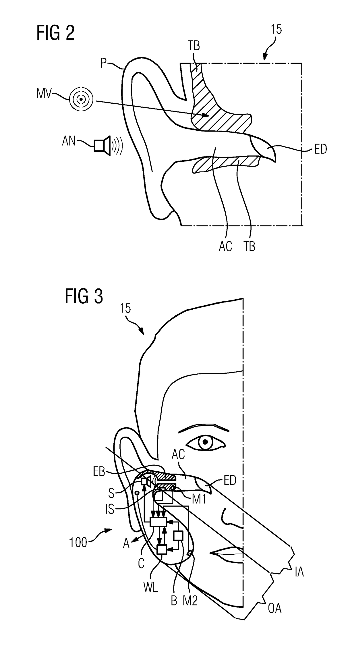
In addition, the microphones that are normally used to pick up the noise inside the magnetic resonance machine are located so far from the ear of the patient that the noise actually occurring inside the ear of the patient is not picked up.
Microphone location may also further limit the noise reduction capability.

Method used


Image

  • Mr audio unit
  • Mr audio unit
  • Mr audio unit

Examples


Embodiment Construction

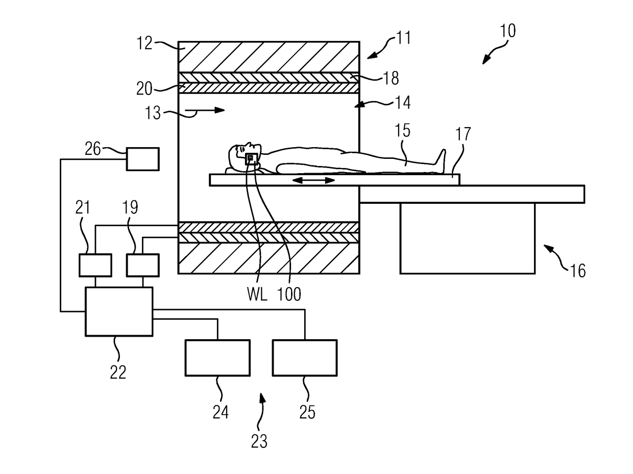
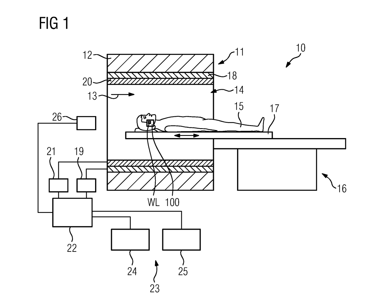
[0105]FIG. 1 shows a diagram of a magnetic resonance system including a magnetic resonance machine 10 and an audio unit 100. The magnetic resonance machine 10 includes a magnet unit 11. Magnet unit 11 includes a main magnet 12 for producing a powerful main magnetic field 13 (e.g., that is constant over time). The magnetic resonance machine 10 also includes a patient receiving zone 14 for accommodating a patient 15. In the present exemplary embodiment, the patient receiving zone 14 is shaped as a cylinder and is enclosed cylindrically in a circumferential direction by a cover of the magnet unit 11. The patient receiving zone 14 may have a different configuration. The patient 15 may be moved into the patient receiving zone 14 by a patient support apparatus 16 of the magnetic resonance machine 10. The patient support apparatus 16 includes a patient couch 17, configured to move inside the patient receiving zone 14.

[0106]The magnet unit 11 further includes a gradient coil unit 18 for gen...


PUM


Abstract

The present embodiments relate to an audio unit for reducing an awareness of a noise produced by a magnetic resonance machine, to an audio system, to a magnetic resonance system, and to a method for operating an audio unit. The audio unit includes a vibration sensor unit, a control unit (e.g., a microcontroller), and at least one loudspeaker. The vibration sensor unit may be configured to detect signals transmitted by bone conduction, and may be configured to transmit the signals to the control unit. The control unit may be configured to control the at least one loudspeaker based on the transmitted signals.

Description

CROSS-REFERENCE TO RELATED APPLICATIONS[0001]The present patent document claims the benefit of EP 16195656, filed on Oct. 26, 2016, which is hereby incorporated by reference in its entirety.TECHNICAL FIELD[0002]The present embodiments relate to an audio unit for reducing an awareness of a noise produced by a magnetic resonance machine, to an audio system and to a magnetic resonance system, and to a method for operating an audio unit.BACKGROUND[0003]Magnetic Resonance Imaging (MRI) is a known technique for producing images of inside a body of a patient and is based on the physical phenomenon of magnetic resonance (MR).[0004]During a MR measurement, gradient coils in a gradient coil unit of a magnetic resonance machine are operated with short, high current pulses (e.g., of amplitude 600 Amperes and having rise and fall times of less than one microsecond). The short, high current pulses generate magnetic field gradients used for encoding signals that are essential to producing images.[...

Claims


Application Information

Patent Timeline
Patent Type & Authority Applications(United States)
IPC IPC(8): G01R33/28
CPCG01R33/283A61B5/055G01R33/28G01R33/288G10K11/178H04R1/10G10K11/1781H04R1/1016H04R1/406H04R2420/07H04R2460/13
Inventor POPESCU, STEFAN
Owner SIEMENS HEALTHCARE GMBH
Learn More