Contoured Support Shoe Insole

Active Publication Date: 2018-04-26
IMPLUS FOOTCARE
View PDF7 Cites 24 Cited by
  • Summary
  • Abstract
  • Description
  • Claims
  • Application Information

AI Technical Summary

Benefits of technology

The present invention provides an improved insole that combines cushioning, support, and motion control for better performance and comfort. The insole includes a unique separation wall, raised dome structures, and a diamond shoe groove pattern for better cushioning and traction. The method of construction involves combining a cushioning core, a stiff support cushion, and other pads to provide stability, control, and prevention of pronation and supination. The size, firmness, and material properties of the pads can be adjusted to address different foot motion issues. The invention is designed for different activities and can provide enhanced cushioning features to various areas of the foot.

Problems solved by technology

The human foot is a very complex biological mechanism.
Like most custom made items, custom insoles tend to be expensive because of the low volume and extensive time needed to make and fit them properly.
As such, it is not practical to make such custom made insoles for the general public.
However, for more strenuous or technically challenging activities, such as carrying a heavy backpack or traversing difficult terrain, a typical cushioning insole will not be adequate.
Under such conditions, a cushioning insole by itself would not provide enough support and control, and tends to bottom out during use by fully compressing the cushioning insole.
The rigid structure is good at controlling motion, but is not very forgiving.
As a result, when motion of the foot reaches a limit imposed by the rigid structure, the load on the foot tends to change abruptly and increases the load on the structures of the foot.
Because biological tissues such as tendons and ligaments are sensitive to the rate at which they are loaded, the abrupt change in load causes injury or damage to the foot, ankle or leg.
These prior art patents, however, do not address the problems of enhanced cushioning and stability, possible movement of the insole during shoe operation, or establishing enhanced cushioning characteristics to address running and walking usages.

Method used


Image

  • Contoured Support Shoe Insole
  • Contoured Support Shoe Insole
  • Contoured Support Shoe Insole

Examples


Embodiment Construction

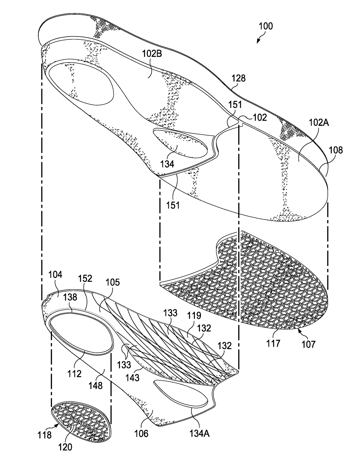
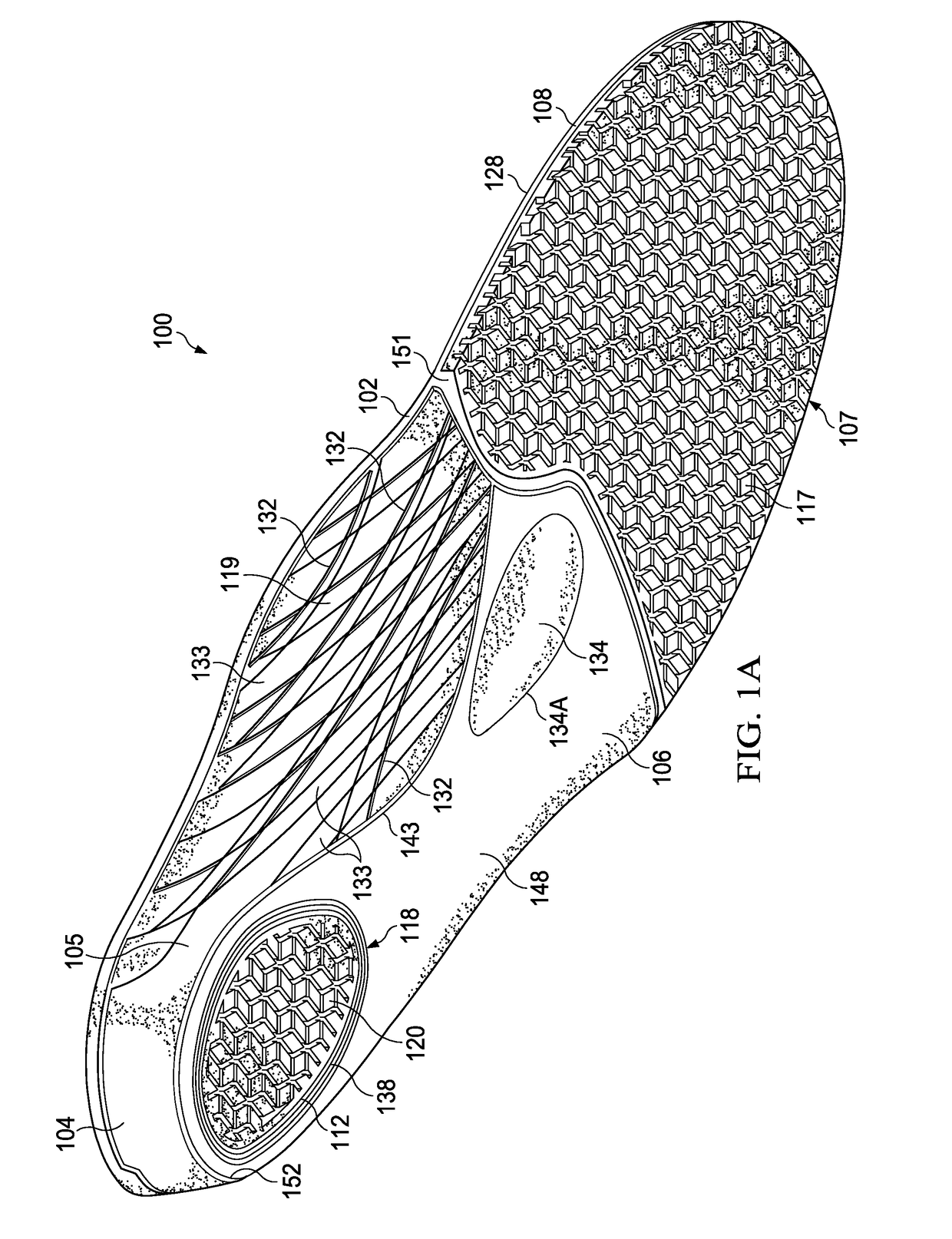
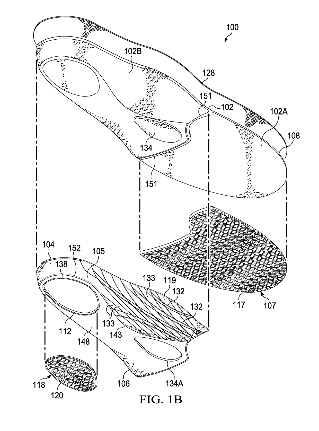
[0030]In accordance with principles of the present invention, the present invention possesses: (1) a base of PU polyester glycol with a hardness of about 30 Asker±3 extending the length and width of the insole curving up in the medial arch area to form an arch support area and curving around the heel area to form a heel cup on the foot contact surface, with a separating wall between the base material and the forefoot pad indentation area on the bottom surface; a heel pad indentation under the calcaneal (heel) area on the bottom surface; a raised arch in the medial arch area with integrally formed longitudinal curvilinear indentations situated lengthwise, the curvilinear indentations formed in a criss-cross pattern alternating with interleaving and integrally formed raised gripping ridges in the medial arch area on the bottom surface; and a teardrop shaped indentation in the metatarsal area of the midfoot which curves upwardly (concave) from the bottom of the base bottom (shoe contac...


PUM


Abstract

An insole having a top sheet and a base layer with three pieces that include a base layer, a forefoot pad made of a clear TPR gel and a mid-foot to heel cushion made of a supersoft polyurethane. The midfoot / heel surface has a raised arch with criss-crossing longitudinal curvilinear indentations, a flattened midfoot area with a metatarsal midfoot tear-drop raised area, and a heel cup that surrounds the exterior back of the heel. A heel pod opening goes through the entirety of the thickness of base layer of the insole body and a heel pad is affixed to the bottom surface of the base layer being made of a clear TPR gel or blown EVA. There is also a supersoft heel dome and a metatarsal raised dome on the top (foot contact) surface of the insole which would be directly above the heel pod and the metatarsal midfoot area, respectively.

Description

CROSS REFERENCE TO RELATED APPLICATIONS[0001]This application claims the benefit of U.S. Provisional Patent Application Ser. No. 62 / 167,753 filed May 28, 2015, U.S. Provisional Patent Application Ser. No. 62 / 181,995 filed Jun. 19, 2015, and U.S. Provisional Patent Application Ser. No. 62 / 214,557 filed Sep. 4, 2015.STATEMENT REGARDING FEDERALLY SPONSORED RESEARCH OR DEVELOPMENT[0002]Not applicable.TECHNICAL FIELD[0003]The present invention relates in general to an improved shoe insole and more particularly to an insole providing improved cushioning and support to the foot of a wearer.BACKGROUND OF THE INVENTION[0004]Insoles are inserted in the shoes of a user to provide one or more advantages to the comfort of the wearer or the support of the foot. Insoles are generally sold in pairs and one of each pair is adapted for use in a right shoe and the other adapted for use in a left shoe of a user. It is advantageous to provide appropriate structure to an insole so that it serves the purp...

Claims


Application Information

Patent Timeline
IPC IPC(8): A43B13/22A43B17/00A43B17/02A43B17/18A43B7/14
CPCA43B13/226A43B17/006A43B17/026A43B17/18A43B7/142A43B7/1445A43B7/141A43B7/1425A43B7/1435A43B7/144A43B7/145A43B7/148A43B13/223A43B7/1475A43B7/14A43B7/1405A43B7/1415
Inventor GRANGER, DAVID BRADLEYMARTINEZ, JACOB
Owner IMPLUS FOOTCARE
Why Eureka
Try Eureka