Electroplating solution analyzer and electroplating solution analysis method
a technology of electroplating solution and analyzer, which is applied in the direction of electrolysis components, material electrochemical variables, cells, etc., can solve the problems of complex operation, additive, decomposing or degenerating, etc., and achieve the effect of accurate determination
- Summary
- Abstract
- Description
- Claims
- Application Information
AI Technical Summary
Benefits of technology
Problems solved by technology
Method used
Image


Examples
example 1
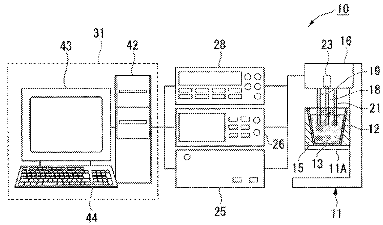
[0242]In Example 1, the conditions of the measurement samples P1 and P2 were determined by use of the electroplating solution analyzer 10.
[0243]The specific configurations and measurement conditions of the electroplating solution analyzer 10 are as follows.
[0244]A platinum disk electrode is used as a working electrode 18. The platinum disk electrode has an area of 4 πmm2.
[0245]An electrode formed from silver / silver chloride (Ag / AgCl) is used as a reference electrode 19. An electrode formed of a cylindrical copper ingot having a diameter of 8 mm is used as a counter electrode 21.
[0246]The measurement conditions of the potential V(t) in the potential measuring unit 28 are as follows: the working electrode 18 has a current density of 1 A / dm2; the working electrode 18 rotates at 2500 rpm; and the measurement samples P1 and P2 are at 30° C. (303.15K) during measurement of the potential V(t).
[0247]The measurement data of the potential V(t) in Example 1 are indicated by a curve 201 (□ symb...
example 2
[0263]In Example 2, conditions of the measurement samples P3 and P4 were determined by use of the electroplating solution analyzer 10.
[0264]The specific configuration and measurement conditions of the electroplating solution analyzer 10 are similar to those of the above Example 1.
[0265]The measurement data of the potential V(t) in Example 2 are indicated by a curve 203 (□ symbols for the measurement sample P3) and a curve 204 (Δ symbols for the measurement sample P4) in FIG. 7. The measurement time tm is 1200 seconds.
[0266]An average potential μ1 in a measurement section [600 secs, 1200 secs] was used as an analysis value for determination on the electroplating solution 13 of Example 2. The equations (3) to (5) were used to calculate the average potential μ1.
[0267]Example 2 is an example in which the average potential μ1 is the only analysis value for determination.
[0268]In a condition for determination on the electroplating solution 13 of Example 2, a numerical value range to be sa...
example 3
[0276]In Example 3, conditions of the measurement samples P5, P6, and P7 were determined by use of the electroplating solution analyzer 10.
[0277]The specific configuration and measurement conditions of the electroplating solution analyzer 10 are similar to those of the above Example 1.
[0278]The measurement data of the potential V(t) in Example 3 are indicated by a curve 205 (□ symbols for the measurement sample P5), a curve 206 (Δ symbols for the measurement sample P2), and a curve 207 (∘ symbols, measurement sample P7) in FIG. 8. The measurement time tm is 1200 seconds.
[0279]A potential-variation rate Δ1 in a measurement section [100 secs, 300 secs] and an average potential μ1 in a measurement section [700 secs, 1200 secs] were used as an analysis value for determination on the electroplating solution 13 of Example 3.
[0280]The equations (1) and (2) were used to calculate the potential-variation rate Δ1. The equations (3) to (5) were used to calculate the average potential μ1.
[0281]...
PUM
 Abstract
Description
Claims
Application Information
 - R&D
- Intellectual Property
- Life Sciences
- Materials
- Tech Scout
- Unparalleled Data Quality
- Higher Quality Content
- 60% Fewer Hallucinations
Browse by: Latest US Patents, China's latest patents, Technical Efficacy Thesaurus, Application Domain, Technology Topic, Popular Technical Reports.
© 2025 PatSnap. All rights reserved.Legal|Privacy policy|Modern Slavery Act Transparency Statement|Sitemap|About US| Contact US: help@patsnap.com