Eureka AIR delivers breakthrough ideas for toughest innovation challenges, trusted by R&D personnel around the world.

Draft Beer Machine

a beer machine and beer technology, applied in the field of beer equipment, can solve the problems of slow refrigeration speed, difficulty in supplying canned or bottled beer to meet people's drink demand, and beer discharge has not been cooled in fact, so as to improve refrigeration efficiency, improve the effect of cooling efficiency, and speed up the cooling function

Active Publication Date: 2018-04-12
TALOS TECH CORP
View PDF5 Cites 3 Cited by
  • Summary
  • Abstract
  • Description
  • Claims
  • Application Information

AI Technical Summary

Benefits of technology

The draft beer machine has a refrigeration circuit that uses conventional refrigeration units and refrigeration tubes to quickly cool the beer. The refrigeration tubes and beer pipes are wound in a helical manner to form a quick cooler, ensuring efficient cooling capacity transfer in the form of dry contact cooling. This design prevents clogging of the tubes and ensures a good refrigeration effect. A thermal conductive medium can be filled in between the two adjacent layers to further improve the efficiency of cooling capacity transfer. The technical effects of this patent are improved quick cooling effect, efficiency of cooling capacity transfer, and prevention of clogging of the tubes.

Problems solved by technology

It has been difficult for canned or bottled beer to meet people's drink demand, and more and more people hope they could drink fresh, hygiene, palatable and pure draft beer.
Although this draft beer machine can achieve the refrigeration of beer, it has the disadvantage of slow refrigeration speed.
Because it takes some time for the temperature of the water in the water tank to drop, when the draft beer machine is switched on, the discharged beer has not been cooled yet in fact.
Therefore, it does not achieve a quick cool in the draft beer machine.

Method used


Image

  • Draft Beer Machine
  • Draft Beer Machine
  • Draft Beer Machine

Examples


first embodiment

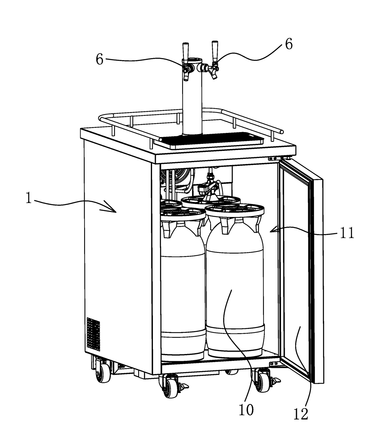
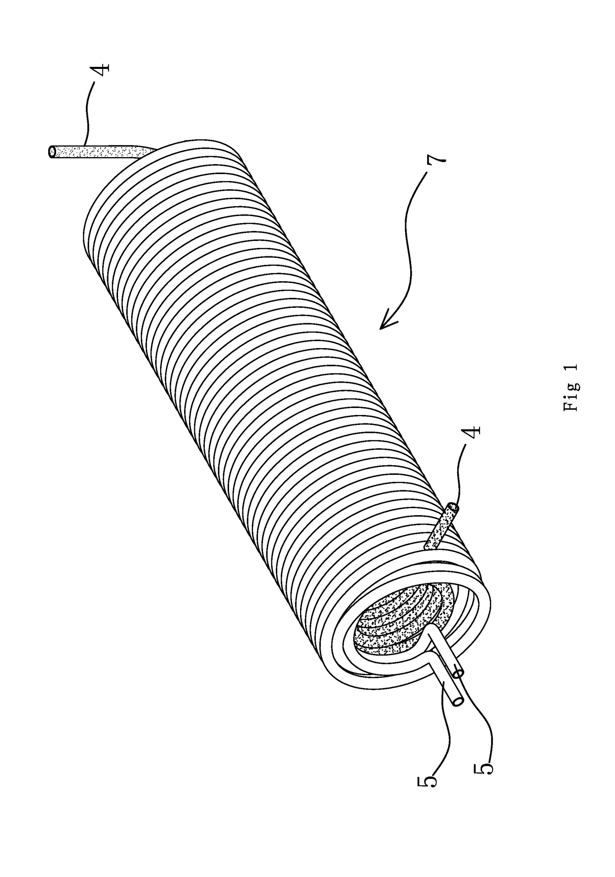
[0037]As shown in FIG. 1 through FIG. 9, one embodiment of a draft beer machine comprises a cabinet (1). The cabinet (1) is overall in a cube shape, and inside the cabinet (1), there is a cold storage chamber (11) used to hold casks (10). A door (12) is also arranged on the cabinet (1) to open or close it conveniently. The cold storage chamber (11) has a single cavity structure, and a refrigeration circuit is arranged inside the cold storage chamber (11). The refrigeration of beer in the beer pipe (5) is achieved by the refrigeration circuit. The refrigeration circuit comprises conventional refrigeration units like a compressor (2), a condenser (3), etc. These refrigeration units are connected to a quick cooler (7) formed by winding refrigeration tubes (4), and can continuously transfer cooling capacity to the refrigeration tubes (4). There are also beer pipes (5) arranged in the cabinet (1). There is a beer tap (6) connected to the outside of the cabinet (1). The outer end of the b...

second embodiment

[0043]The structure and principle of this embodiment is basically the same as that of the first embodiment. The differences are:

[0044]As shown in FIG. 10, the quick cooler (7) is formed by winding one refrigeration tube (4) and one beer pipe (5). The refrigeration tube (4) adheres both sides of each beer pipe (5) inside the wound helical coil. The refrigeration effect is better.

third embodiment

[0045]The structure and principle of this embodiment is basically the same as that of the first embodiment. The differences are:

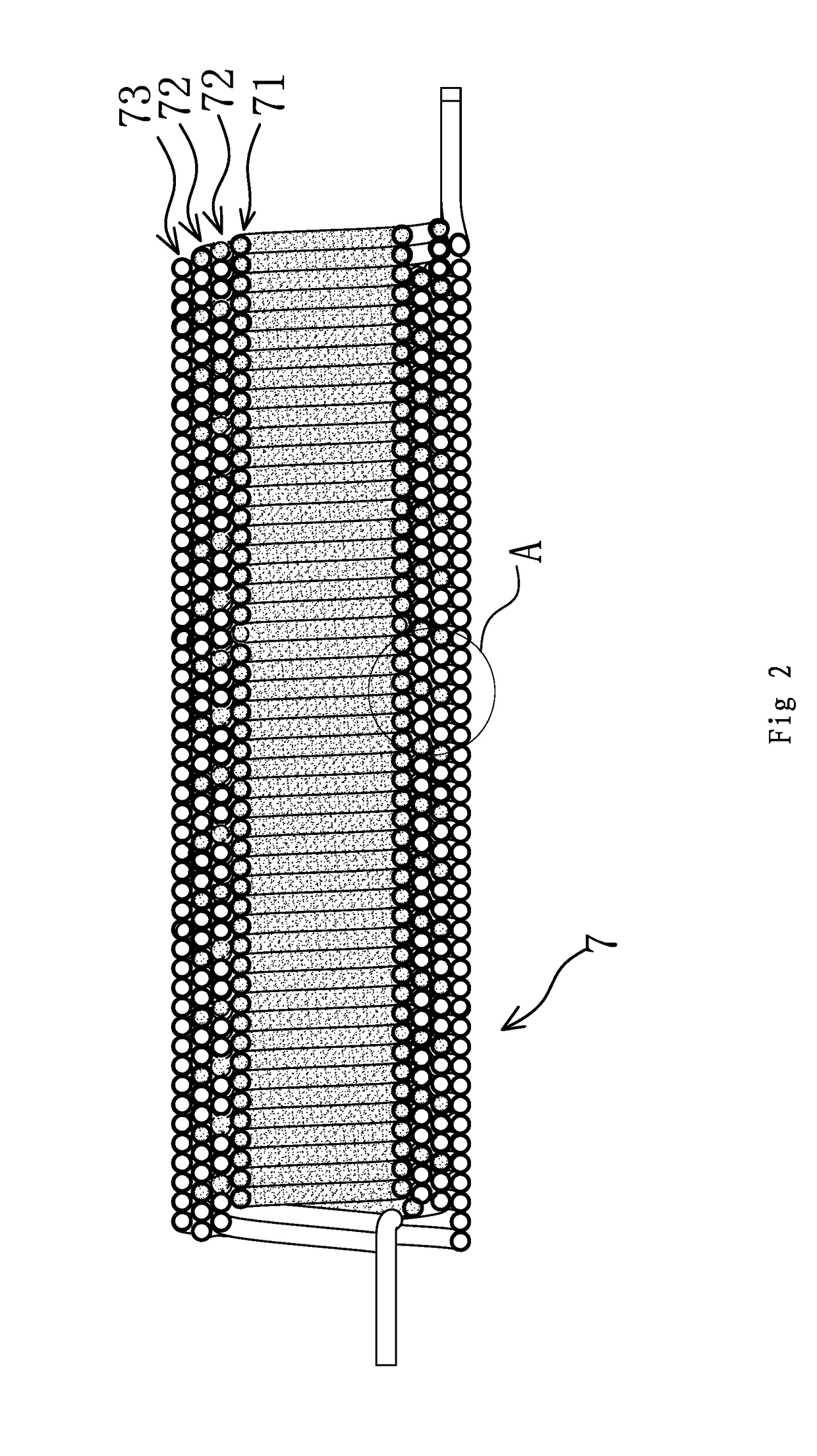
[0046]The two adjacent tube layers do not directly adhere; instead, a thermal conductive medium is filled in between the two layers. The thermal conductive medium is thermal conductive mud. Namely, the thermal conductive mud is filled in between the beer pipe layer (73) and the outermost mixing layer (72), between the adjacent mixing layers (72), and between the innermost mixing layer (72) and the refrigeration layer (71). The thermal conductive mud can be kneaded into various shapes as required, and be filled in between two adjacent tube layers. This allows two tube layers to adhere tightly, reduce the thermal resistance and transfer cooling capacity quickly and effectively to refrigerate beer, so as to improve the refrigeration efficiency of beer. Of course, aluminum powder has a fairly good thermal conductivity and it can effectively transfer cooling cap...


PUM


Abstract

A draft beer machine comprising a cabinet and a refrigeration circuit inside the cabinet, including a compressor, a condenser, and refrigeration tubes. Beer pipes are also arranged inside the cabinet and a beer tap is fixed to the outside of the cabinet. The outer end of the beer pipes is connected to the beer tap. The refrigeration tube and the beer pipe are wound into a quick cooler of a round or an elliptic cylindrical shape, in a helical manner. The quick cooler comprises at least one mixing layer, which is formed by winding the refrigeration tube and the beer pipe into a round or elliptic cylinder, in an abreast and helical manner. In the same mixing layer, the adjacent beer pipe and refrigeration tube adhere to each other. The adjacent two mixing layers directly adhere or a thermal conductive medium is filled in between the two layers.

Description

RELATED APPLICATIONS[0001]This application claims benefit of Chinese Patent Application No. CN 201610887329.3, filed Oct. 11, 2016.[0002]The applications and all patents, patent applications, articles, books, specifications, other publications, documents, and things referenced herein are hereby incorporated herein in their entirety for all purposes. To the extent of any inconsistency or conflict in the definition or use of a term between any of the incorporated publications, documents, or things and the text of the present document, the definition or use of the term in the present document shall prevail.BACKGROUND OF THE INVENTIONField of Invention[0003]The present invention relates to the technical field of beverage equipment, and particularly to a draft beer machine.Related Art[0004]With the progress of the times, and the improvement of people's quality of life, people have a higher requirement for drinking beer. It has been difficult for canned or bottled beer to meet people's dr...

Claims


Application Information

Patent Timeline
Patent Type & Authority Applications(United States)
IPC IPC(8): B67D1/08F25D11/00F25D31/00B67D1/00
CPCB67D1/0868F25D11/00F25D2400/28B67D1/0891B67D1/0004F25D31/002B67D1/0858B67D2210/00133B67D2210/00049
Inventor QIU, DIQINGQIU, DILIN
Owner TALOS TECH CORP
Why Eureka
Eureka Blog
Learn More