Shoulder Prosthesis With Variable Inclination Humeral Head Component

a humeral head and shoulder prosthesis technology, applied in the field of shoulder prosthesis with variable inclination humeral head component, can solve the problems of significant component malposition, method disadvantage, and inability to accurately and efficiently design a variable inclination system.

Active Publication Date: 2018-04-05
MAYO FOUND FOR MEDICAL EDUCATION & RES
View PDF5 Cites 19 Cited by
  • Summary
  • Abstract
  • Description
  • Claims
  • Application Information

AI Technical Summary

Benefits of technology

The invention is a humeral head assembly with a taper that allows for adjusting the inclination and version of a shoulder prosthesis. This eliminates the need for separate stems and reduces the inventory of components. The proper range of inclination can be determined through patient studies, and the invention addresses deficiencies in current systems by providing a variable inclination system based on anatomical distribution. The method can also be applied to other joints such as the glenosphere and femoral head.

Problems solved by technology

However, a review of competitive systems in the marketplace reveals that the range of inclination provided by these systems does not properly address the range of humeral head component inclination encountered at the time of shoulder arthroplasty.
In addition, many of the ranges provided by shoulder arthroplasty systems are not physiologic and may result in significant component malposition.
In addition to a lack of understanding of the proper range of inclination necessary for a humeral component, the method to achieve this inclination has associated challenges.
Each of these methods has disadvantages.
However, this can result in a significant increase in inventory requiring multiple stem inclinations for a wide breadth of stem diameters.
This can make the set screw the “weak link” in the design and could be problematic during attempted removal.
This can result in making humeral head component removal impossible without removing the humeral stem.
However, the lateral opening in the humeral stem remains, making removal of the humeral stem much more difficult if used with cement.
This method also does not allow one to place the stem in the humeral canal independent of the humeral head component.

Method used


Image

  • Shoulder Prosthesis With Variable Inclination Humeral Head Component
  • Shoulder Prosthesis With Variable Inclination Humeral Head Component
  • Shoulder Prosthesis With Variable Inclination Humeral Head Component

Examples


Embodiment Construction

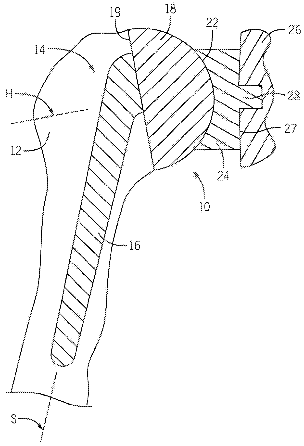
[0085]Looking first at FIG. 1, there is shown an example conventional shoulder prosthesis 10. The upper portion of the humerus 12 is replaced by a humeral component 14 including a stem 16 that extends into a bore formed within the humerus 12. Typically, the stem 16 is fixed within the bore formed within the humerus 12. The stem 16 has a longitudinal stem axis S. A generally hemispherical head 18 is connected to the stem 16. Alternatively, the head 18 is integral with the stem 16. The hemispherical head 18 has a base surface 19 and a longitudinal head axis H. The hemispherical head 18 of the humeral component 14 articulates with a complementary concave section 22 of a glenoid component 24 that is fixed within the glenoid cavity of the scapula 26 using cemented or uncemented posts 28. The glenoid component 24 includes a base surface 27 opposite the concave section 22 that serves as an articular surface of the glenoid component 24.

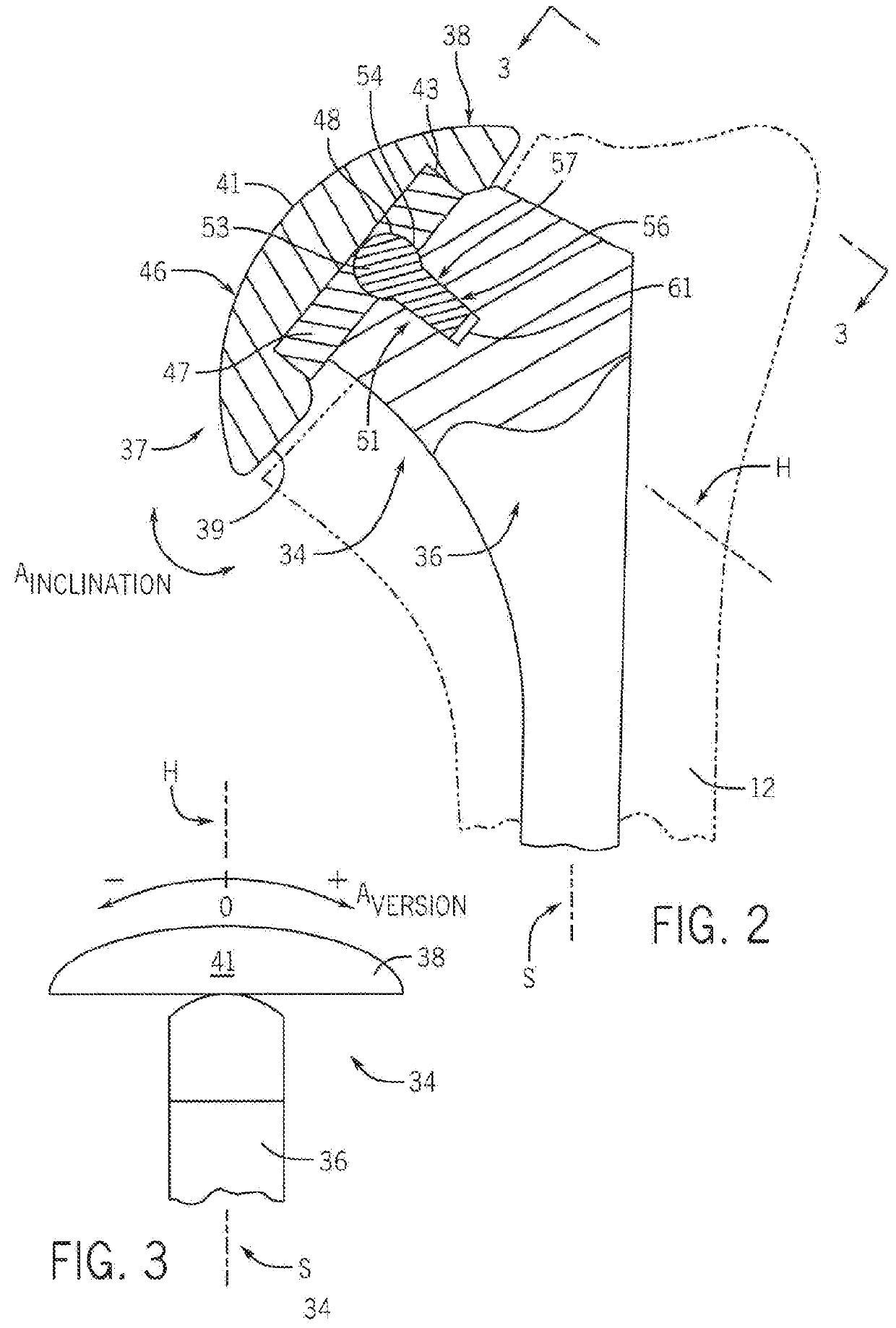
[0086]Referring now to FIGS. 2-3, there is shown an exa...


PUM


Abstract

Methods and devices are disclosed for joint (e.g., shoulder) arthroplasty, including for reverse joint arthroplasty. In one aspect, there is provided a trial device for determining inclination, offset, and / or version of a prosthetic tray with respect to a prosthetic stem or stemless implant. In another aspect, there is provided a joint (e.g., shoulder) prosthesis, which allows for variable offset, inclination or version or any combination thereof. In another aspect, there is provided a method for setting an offset or inclination angle or a version angle or any combination thereof of a prosthetic tray with respect to a stem or stemless device implanted or to be implanted in a bone of a joint (e.g., shoulder) by matching the corresponding offset or version or inclination or any combination thereof to a trial device.

Description

CROSS-REFERENCES TO RELATED APPLICATIONS[0001]This application is a continuation-in-part application of U.S. patent application Ser. No. 14 / 773,605 filed Sep. 8, 2015, which is a 371 application of PCT / US2014 / 020308 filed Mar. 4, 2014 which claims priority to U.S. Patent Application No. 61 / 774,969 filed Mar. 8, 2013, all of which are incorporated herein by reference. This application also claims priority to U.S. Patent Application No. 62 / 430,443 filed Dec. 6, 2016, which is incorporated herein by reference.STATEMENT REGARDING FEDERALLY SPONSORED RESEARCH[0002]Not Applicable.BACKGROUND OF THE INVENTION1. Field of the Invention[0003]The invention relates to a prosthesis and method for variable inclination, and / or offset, and / or version of the humeral tray, head, or glenosphere for shoulder arthroplasty, or radial head, ulna, or humerus for the elbow, or femoral head or acetabular component for hip arthroplasty, or tibial or femoral component for knee arthroplasty, or tibial or talar c...

Claims


Application Information

Patent Timeline
IPC IPC(8): A61F2/46A61F2/30A61F2/44A61F2/42A61F2/40A61F2/38A61F2/36
CPCA61F2/4657A61F2/4684A61F2/30749A61F2/44A61F2/4202A61F2/4014A61F2/3859A61F2/3804A61F2/3609A61F2002/3071A61F2/4637A61F2002/30649A61F2002/30329A61F2002/4668A61F2002/4205A61F2002/3831A61F2002/3827A61F2002/3822A61F2002/4681A61F2002/30538A61F2002/30617A61F2002/4037A61F2002/30378A61F2002/30553
Inventor SPERLING, JOHN W.TREAT, AARON C.KLINE, BRUCE R.LARSON, MICHAEL B.DENNIS, KENDALL
Owner MAYO FOUND FOR MEDICAL EDUCATION & RES
Why Eureka
Try Eureka