
Automatic, Highly Reliable, Fully Redundant Electronic Circuit Breaker That Reduces or Prevents Short-Circuit Overcurrent

a technology of electronic circuit breakers and circuit breakers, applied in the field of electronic fuses, can solve problems such as failure to reduce the entire system voltage or even melt the mosfet, and failure to provide any protection or redundancy

Active Publication Date: 2018-03-22
REDLER TECH LTD
View PDF0 Cites 276 Cited by
  • Summary
  • Abstract
  • Description
  • Claims
  • Application Information

AI Technical Summary

Benefits of technology

The patent text describes an improved electronic fuse that can quickly protect energy sources and switching elements from high currents during short circuits or open loads. It also ensures the reliability and isolation of a MOSFET, and fits into a standard fuse holder. This solves a long-felt but unmet need.

Problems solved by technology

These systems fail to provide any protection or redundancy within the relevant switch if the MOSFET malfunctions, however.
Moreover, if there is a delay between the detection of the short circuit and the disconnection of the load branch from the energy source, the MOSFET, the shorted load, and the power source are exposed to the overcurrent, which may reduce the entire system voltage or even melt the MOSFET.
The relatively high internal resistance of batteries and fuel cells puts constraints on the system reliability, however, because these types of fuses cannot act quickly enough to prevent the battery from experiencing a high current surge from which the fuses are damaged.
For example, if the energy source is a 24 V battery with an internal resistance of 0.5Ω, a short circuit of 50 A for 1 mSec causes a short to the battery, causing some or all loads in the electric switching system to lose energy.
Due to the high short circuit current, connecting capacitors near the battery does not provide a practical solution to the problem.
Similarly, if the energy source is, for example, a 24 V vehicle battery with an internal resistance of 1 mΩ connected to a MOSFET having an internal resistance of 5 mΩ, a short circuit conducts a current of 24 V / 0.006Ω=4000 A. Thus, a delay prior to detection of the short circuit of 1 ms causes a short to the battery, causing some or all loads in the electric switching system to lose energy.
In cases in which the power source has a high impedance, power switching systems known in the art generally introduce significant undesired surge current into the circuit.
Such an event melts the transistor and permanently shorts the load.

Method used

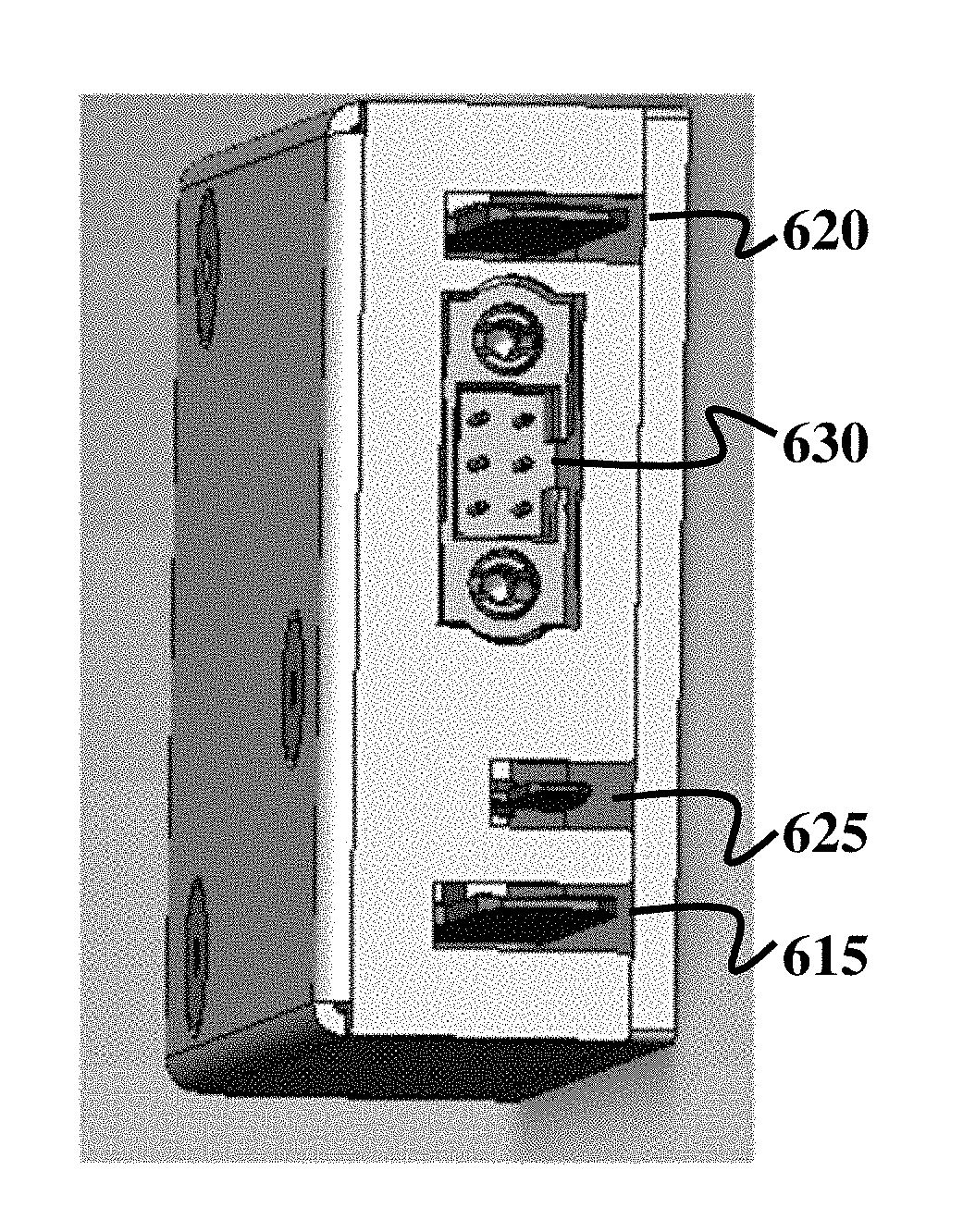
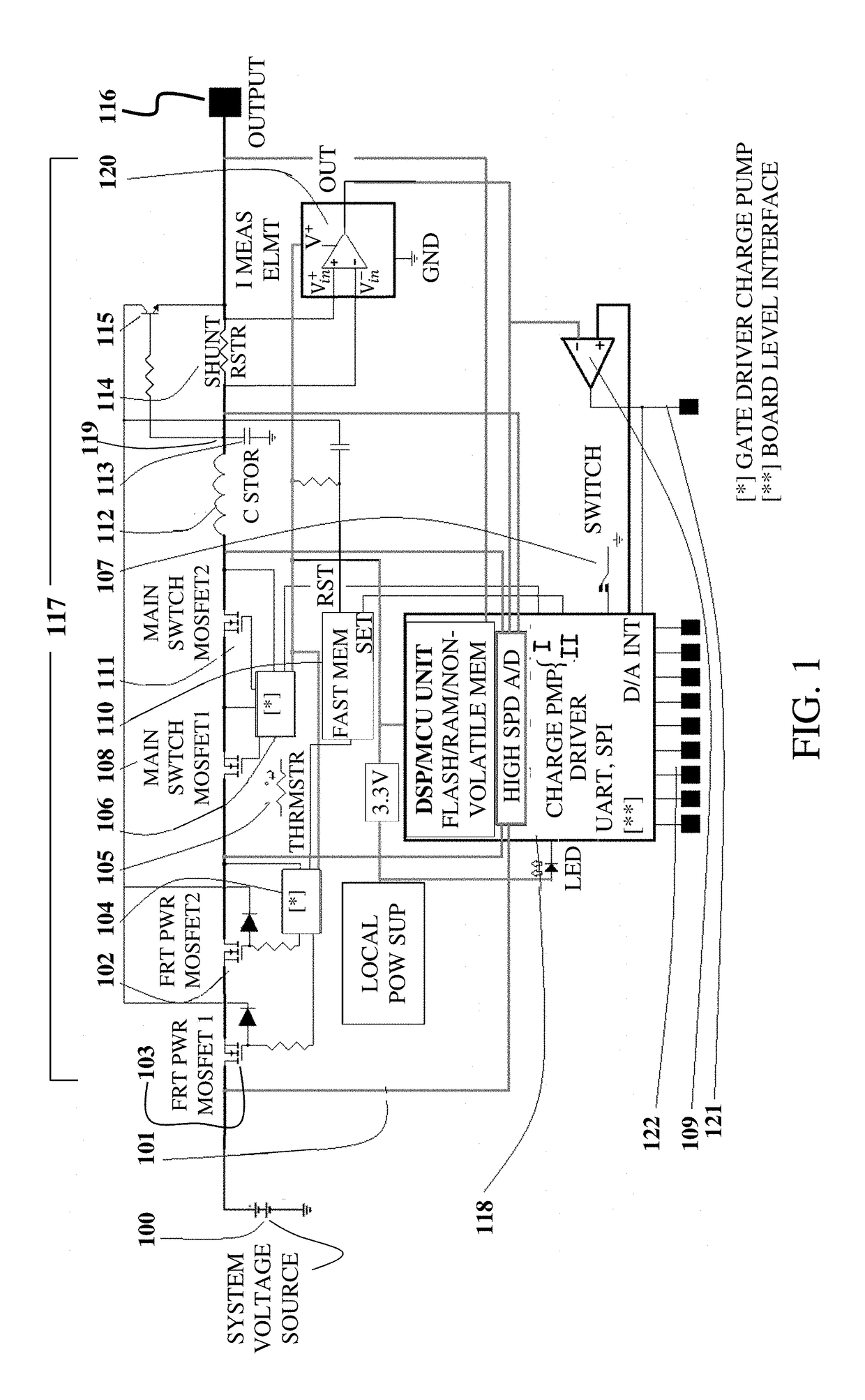
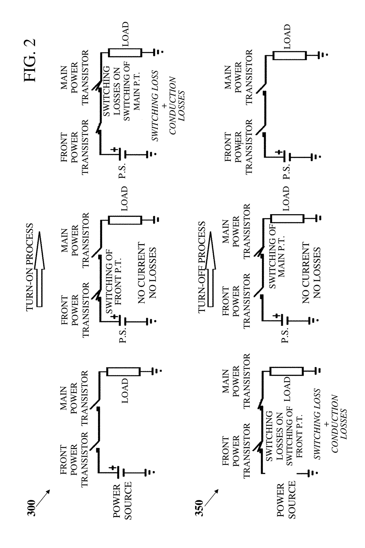

Image

  • Automatic, Highly Reliable, Fully Redundant Electronic Circuit Breaker That Reduces or Prevents Short-Circuit Overcurrent
  • Automatic, Highly Reliable, Fully Redundant Electronic Circuit Breaker That Reduces or Prevents Short-Circuit Overcurrent
  • Automatic, Highly Reliable, Fully Redundant Electronic Circuit Breaker That Reduces or Prevents Short-Circuit Overcurrent

Examples


Embodiment Construction

[0041]In the following description, various aspects of the invention will be described. For the purposes of explanation, specific details are set forth in order to provide a thorough understanding of the invention. It will be apparent to one skilled in the art that there are other embodiments of the invention that differ in details without affecting the essential nature thereof. Therefore the proper scope of the invention is to be understood only as indicated in the accompanying claims, and determined only by the broadest interpretation of said claims.

[0042]As used herein, with regard to numerical quantities, the term “about” refers to a value within ±25% of the nominal value.

[0043]The electronic fuse (Programmable Power Switching Element or PPSE) disclosed herein enables measurement, management, control, protection, and isolation of branch loads from the energy source along with high surge current limits of the current that passes through the circuit and transistors. A plurality of...


PUM


Abstract

A programmable power (PPSE) switching element including a front power transistor, a main switching transistor, and at least one reverse current blocking transistor in series, a gate of each of which is connected to a gate driver; an inductor and a shunt resistor connected in series with the transistors; a charge storage capacitor connected between ground and a junction located between the inductor and the shunt resistor; a high-speed NPN transistor, a collector of which is connected to the front power transistor and an emitter of which is connected to an output of the main switching transistor via the shunt resistor; a current measurement element in parallel to the shunt resistor; a voltage amplifier; and a high-speed MCU.

Description

CROSS-REFERENCE TO RELATED APPLICATIONS[0001]This application is filed under 35 U.S.C. 111(a) and C.F.R. 1.53 as a Continuation-in-Part of International (PCT) Pat. Appl. No. PCT / IL2016 / 050281, filed 14 Mar. 2016, and claims priority from Israel Pat. Appl. No. 237775, filed 16 Mar. 2015, each of which is incorporated herein by reference in its entirety.FIELD OF THE INVENTION[0002]Disclosed embodiments relate in general to electronic fuses, and in particular, to programmable electronic fuses that reduce or prevent high current flow under short circuit conditions, eliminate power source current surges, reduce or prevent switching element destruction, and increase total fuse reliability.BACKGROUND OF THE INVENTION[0003]Conventional Programmable Power Switching Systems (PPSS) and Programmable Power Switching Elements (PPSE) and methods are used for both AC and DC current applications. Such systems are variously known as “smart power switches,”“protection systems,”“electronic fuses,” etc....

Claims


Application Information

Patent Timeline
IPC IPC(8): H02H3/05H02H3/08H02H9/02H03K17/687G01R31/02
CPCH02H3/05H02H3/08H02H9/02H03K17/687G01R31/025H02H3/085H02H3/087G01R31/52
Inventor REDLER, YESAIAHU
Owner REDLER TECH LTD
Learn More