
Rechargeable battery and method for manufacturing the same

a rechargeable battery technology, applied in the field of rechargeable batteries, can solve the problems of loss of functionality, high cost of manufacturing process, and many proposed solutions that are not readily scalable to high yield industrial production levels for commercialization, and achieve the effect of reducing capacity fading and increasing storage capacity per unit weigh

Active Publication Date: 2018-03-22
NEDERLANDSE ORG VOOR TOEGEPAST-NATUURWETENSCHAPPELIJK ONDERZOEK (TNO)
View PDF0 Cites 17 Cited by
  • Summary
  • Abstract
  • Description
  • Claims
  • Application Information

AI Technical Summary

Benefits of technology

The present invention provides a rechargeable battery with a silicon anode material that has improved storage capacity per unit weight and reduced capacity fading. This is achieved by the plurality of columns and interfaces between them that facilitate lithium ion (de)intercalation in or out of the anode layer. The method of the present invention is a self-organizing and spontaneous process for forming a continuous amorphous layer nanostructured with a plurality of columns and interfaces there between, yielding a rechargeable battery with increased storage capacity per unit weight and a reduced capacity fading. The method is a single step manufacturing process without the need for pre- or post-treatment method steps for e.g. the substrate and / or the silicon anode layer, thereby facilitating industrial production levels for commercialization.

Problems solved by technology

One of the main problems with bulk silicon anode material is that it pulverizes quickly during the intercalation process and that it loses its functionality after a relatively small number of charging cycles.
Many of the proposed solutions to manufacture silicon anode material are unattractive as various complex manufacturing steps are required, making the manufacturing process rather expensive.
Also, many of the proposed solutions are not readily scalable to high yield industrial production levels for commercialization.

Method used


Image

  • Rechargeable battery and method for manufacturing the same
  • Rechargeable battery and method for manufacturing the same
  • Rechargeable battery and method for manufacturing the same

Examples


Embodiment Construction

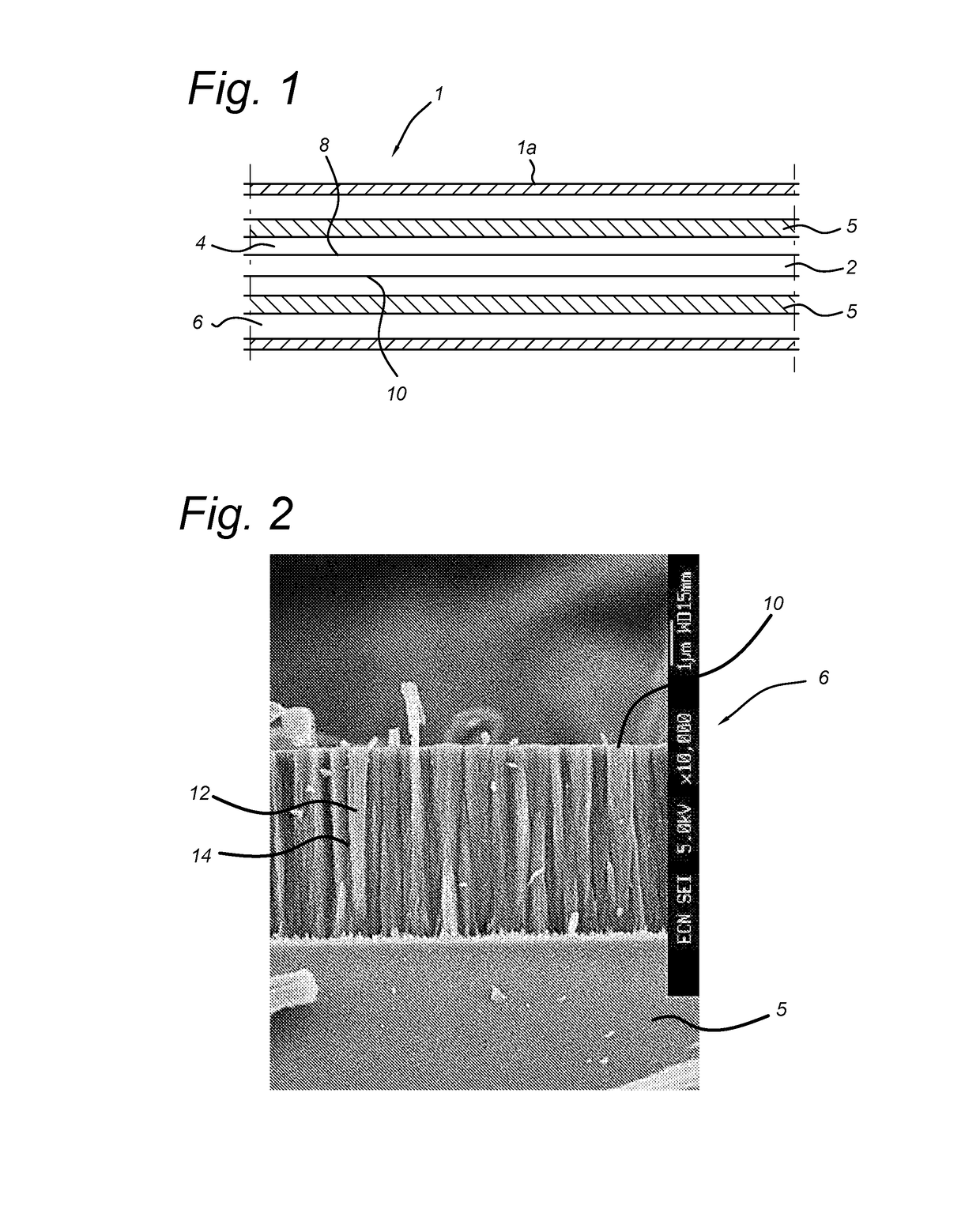
[0028]FIG. 1 shows a cross section of an embodiment of a rechargeable battery 1 according to the present invention. In the embodiment shown, the rechargeable battery 1 comprises at least an electrolyte layer 2, a cathode layer 4 and an anode layer 6, wherein said layers 2, 4, 6 are enclosed by a housing 1a. The electrolyte layer 2 comprises a lithium salt compound that is arranged between a cathode surface 8 of the cathode layer 4 and an anode surface 10 of the anode layer 6. The cathode layer 4 as well as the anode layer 6 are each arranged on a respective substrate 5.

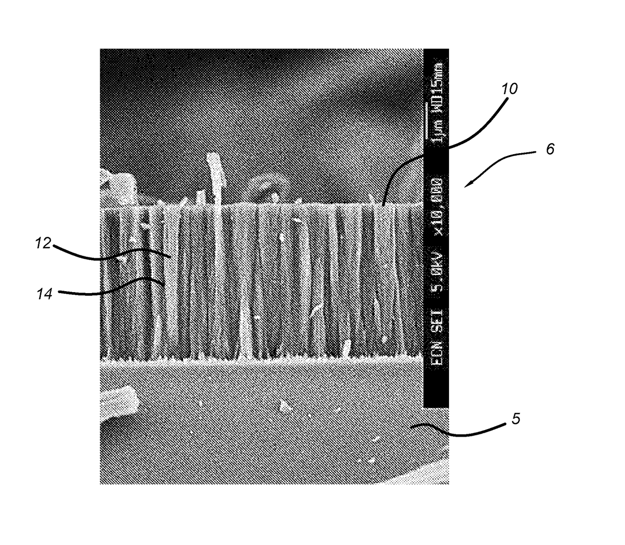
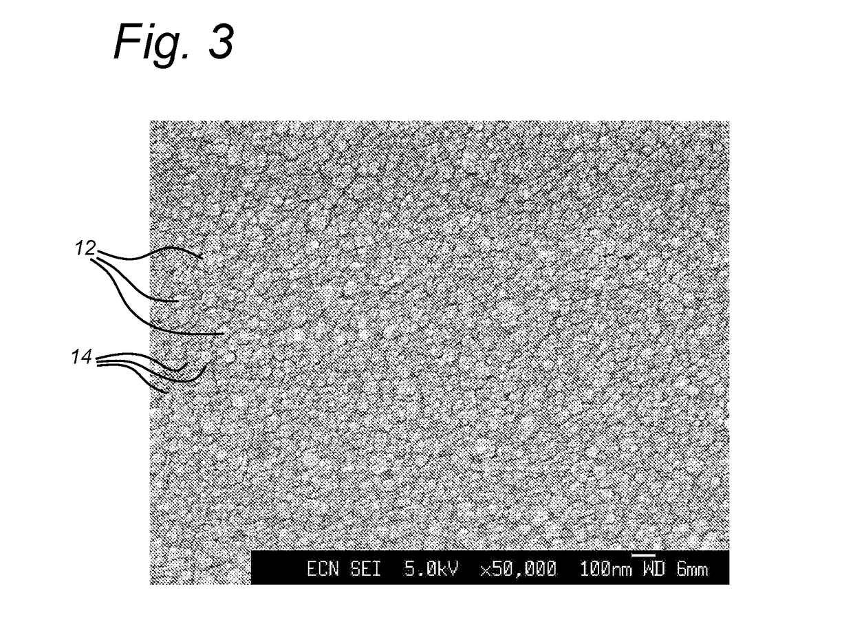
[0029]In FIG. 2 an exemplary embodiment of an anode layer according to the invention is shown. The anode layer 6 comprises a nanostructured silicon thin film layer comprising a plurality of silicon columns 12 or columns 12 arranged on the substrate 5. The nanostructured silicon thin film layer has a measured crystal fraction of zero or substantially zero, so the nanostructured silicon thin film layer comprises amorpho...


PUM

PropertyMeasurementUnit
porosityaaaaaaaaaa
lengthaaaaaaaaaa
lengthaaaaaaaaaa

Abstract

A rechargeable battery includes at least an electrolyte layer, a cathode layer and an anode layer. The electrolyte layer includes a lithium salt compound arranged between a cathode surface of the cathode layer and an anode surface of the anode layer. The anode layer is a nanostructured silicon containing thin film layer including a plurality of columns, wherein the columns are directed in a first direction perpendicular or substantially perpendicular to the anode surface of the silicon thin film layer. The columns are arranged adjacent to each other while separated by grain-like column boundaries running along the first direction. The columns include silicon and have an amorphous structure in which nano-crystalline regions exist.

Description

FIELD OF THE INVENTION[0001]The present invention relates to a rechargeable battery, in particular a lithium-ion rechargeable battery provided with silicon-based anode material. In a further aspect the present invention relates to a method of manufacturing a rechargeable battery.PRIOR ART[0002]Current state of the art lithium-ion batteries typically employ graphite as anode material, wherein storage capacity of graphite is around 370 mAh / g. It is known that silicon anode material has a much larger theoretical capacity of around 4200 mAh / g, but the intercalation process of lithium leads to a volume increase of the silicon anode material as high as 300% or even more. One of the main problems with bulk silicon anode material is that it pulverizes quickly during the intercalation process and that it loses its functionality after a relatively small number of charging cycles.[0003]In order to deal with the volume expansion of silicon anode material and to reduce cracking and pulverization...

Claims


Application Information

Patent Timeline
Patent Type & Authority Applications(United States)
IPC IPC(8): H01M4/134H01M10/0562H01M10/0525H01M4/38H01M4/66H01M4/04
CPCH01M4/134H01M10/0562H01M10/0525H01M4/386H01M4/661H01M4/0423H01M2300/0068H01M2004/021C23C16/24C23C16/511H01M4/0428H01M4/1395H01M4/364B82Y30/00Y02E60/10Y02P70/50
Inventor SOPPE, WILHELMUS JOZEF
Owner NEDERLANDSE ORG VOOR TOEGEPAST-NATUURWETENSCHAPPELIJK ONDERZOEK (TNO)
Learn More