Precision Operator for an Aircraft Autothrottle or Autopilot System

a technology of aircraft autopilot and operator, which is applied in the direction of instruments, actuated personally, transportation and packaging, etc., can solve the problem of relatively light invention arrangement, and achieve the effect of safe and easy override and easy installation in the aircra

Active Publication Date: 2018-03-22
INNOVATIVE SOLUTIONS & SUPPORT
View PDF0 Cites 3 Cited by
  • Summary
  • Abstract
  • Description
  • Claims
  • Application Information

AI Technical Summary

Benefits of technology

[0009]The disclosed embodiments are directed to an aircraft autopilot / autothrottle operator arrangement that is compact, lightweight, reliable and readily installable in an aircraft, even in aircraft in which no special accommodation for adding or providing autopilot / autothrottle capabilities have been designed into or provided for the aircraft, and which can be safely and easily overridden by a pilot wishing to quickly assume manual control of the throttle(s) when under the control of the autopilot / autothrottle system. The disclosed embodiments provide such an operator arrangement that can also be applied, with like advantageous functionality, as part of or in conjunction with an aircraft autopilot system to control the movements of control surfaces of the aircraft whose variable positions are adjustable to control, for example, the pitch, roll and yaw of the aircraft.
[0010]The disclosed embodiments provides an aircraft autopilot / autothrottle operator that exhibits a number of significant advantages over those currently in widespread use. First, the inventive arrangement is relatively lightweight, especially as compared to current autopilot / autothrottle operating arrangements and components. Second, the inventive arrangement is notably simplified, as compared to current autopilot / autothrottle operating arrangements, which can provide significant increases in physical and operating reliability. Third, the inventive arrangement is notably more compact than current autopilot / autothrottle operating arrangements and is therefore installable in a wider range of aircraft of widely varying size. Fourth, the inventive arrangement is based on the use of a linear operator that is activated from a position remote from the throttle handle pivot, thus allowing its installation—either at the time of initial construction or as an add-on or retrofit to an existing structure—in aircraft having a relatively compact throttle quadrant or that have not otherwise been specially designed to accommodate a conventional autopilot / autothrottle and its heavy-duty motors and clutches and which would otherwise be mounted at and proximate the pivot points of the throttle handles. Fifth, the actuator utilized in the inventive arrangement does not require separate or integrated clutches or clutch components and instead provides inherent override capabilities, and neither does it require a series of gears between an operating motor and its attachment to the throttle handle—thereby greatly decreasing complexity, weight and physical space requirements and increasing operating reliability.

Problems solved by technology

First, the inventive arrangement is relatively lightweight, especially as compared to current autopilot / autothrottle operating arrangements and components.

Method used


Image

  • Precision Operator for an Aircraft Autothrottle or Autopilot System
  • Precision Operator for an Aircraft Autothrottle or Autopilot System
  • Precision Operator for an Aircraft Autothrottle or Autopilot System

Examples


Embodiment Construction

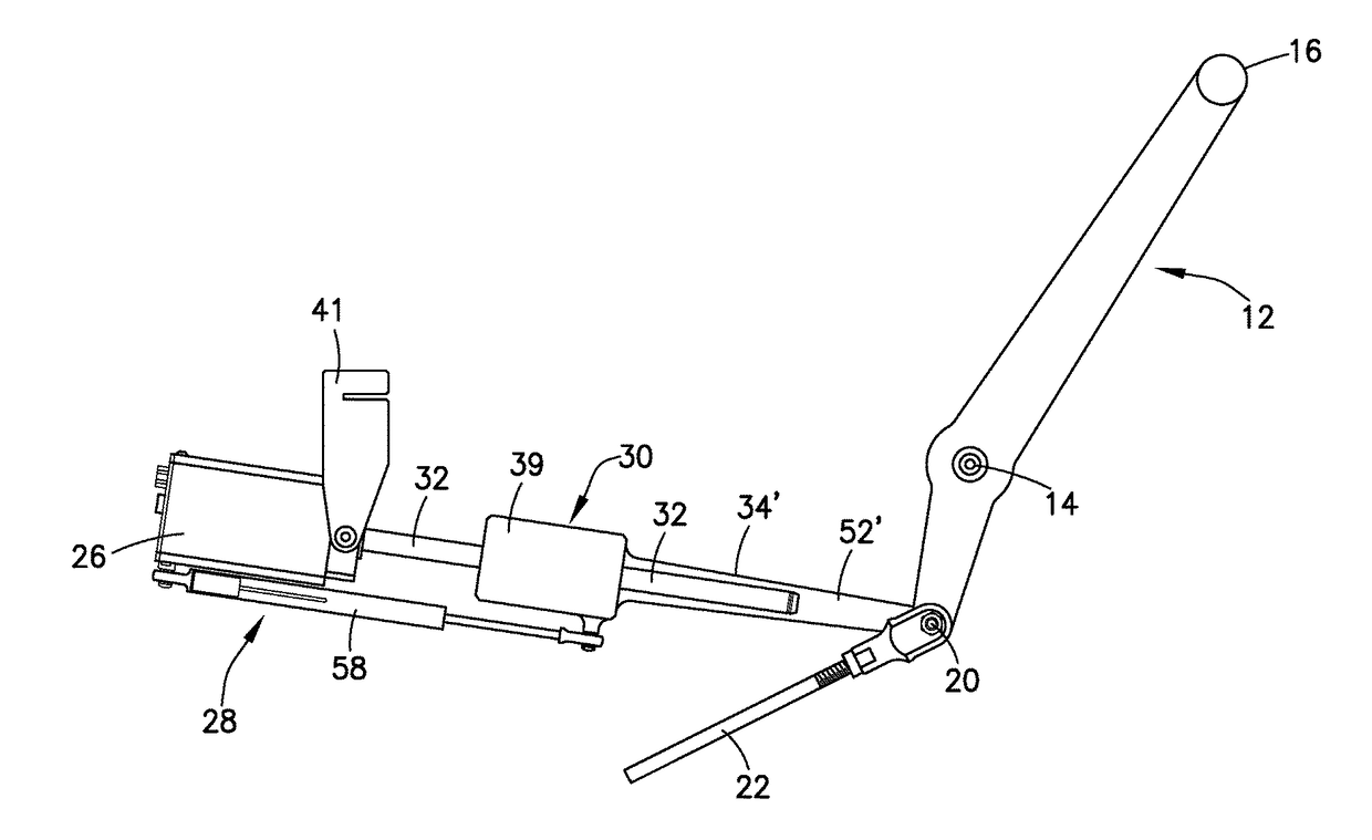
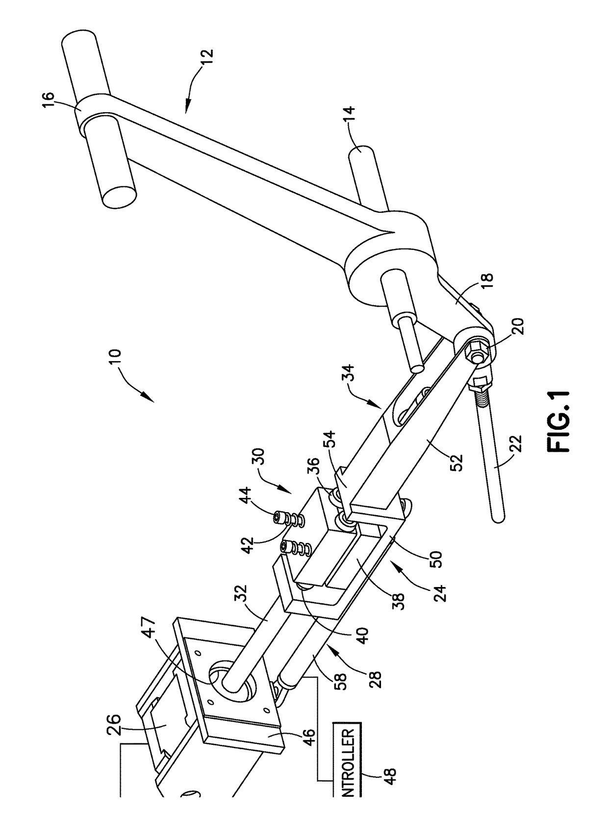
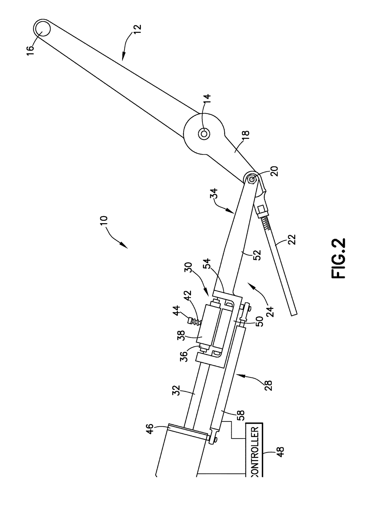
[0022]FIGS. 1 and 2 present two views of an embodiment of the precision aircraft autothrottle operator. The autothrottle operator system or arrangement, identified in the drawing figures by the general reference numeral 10, is attached for use to a conventional throttle handle or lever 12 of an aircraft. The throttle lever 12, the configuration and construction of which is conventional, is mounted for pivoted movement or displacement about a shaft or other pivot point or fulcrum 14 at which the lever 12 is secured in place at the throttle quadrant (not shown) of the aircraft. The distal end 16 of throttle lever 12 is configured—for ease of grasping and manipulation, to advance and retard the lever 12 through its arcuate range of displacement, by a pilot manually controlling the power output of the associated aircraft engine and, thereby, the airspeed or velocity of the aircraft. The opposite or proximal end 18 of throttle lever 12 connects at attachment pin or shaft or point 20 at o...


PUM


Abstract

An autothrottle system for an aircraft includes a motor, actuator assembly, and position sensor operatively connected between the motor and a moving portion of the actuator assembly. An electronic controller is configured to control the motor to move the actuator assembly to actuator positions based at least on position information from the position sensor to move the throttle lever to lever positions. The actuator assembly includes a bearing assembly having a plurality of bearings to contact a surface of a shaft for converting rotational movement of the shaft into linear motion of the bearing assembly along the shaft. The actuator assembly further includes a shuttle arm having at one end a mounting surface to attach to the bearing assembly and at the other end a linkage arm operatively coupled to the attachment end of the lever.

Description

CROSS-REFERENCE TO RELATED APPLICATION[0001]This application claims priority to U.S. Provisional Patent Application No. 62 / 250,819, entitled “Precision Operator for an Aircraft Autothrottle or Autopilot System,” filed Nov. 4, 2015; and U.S. Provisional Patent Application No. 62 / 336,200, entitled “Precision Operator for an Aircraft Autothrottle or Autopilot System,” filed May 13, 2016, both of which are incorporated herein by reference in their entirety.FIELD OF THE INVENTION[0002]The disclosed embodiments relate to an aircraft autopilot system. In particular, the disclosed embodiments relate to a precision operator for an aircraft autopilot system, and more specifically to an arrangement by which selective control for automated mechanical adjustment of aircraft throttle controls and / or aircraft flight control surfaces can be effected while accommodating ready manual override of the automated operator when deemed necessary or otherwise at the behest of the pilot or other operator of ...

Claims


Application Information

Patent Timeline
Patent Type & Authority Applications(United States)
IPC IPC(8): B64D31/14B64D31/12B64D31/10B64C13/10B64D31/04
CPCB64D31/14B64D31/12B64D31/10B64C13/10B64D31/04B64D31/06H02K7/08H02K37/00G07C5/0816
Inventor HEDRICK, GEOFFREY S.M.
Owner INNOVATIVE SOLUTIONS & SUPPORT
Why Eureka
Try Eureka