Method for manufacturing linear cutter, and roller die device for molding linear cutter

a technology of roller die and linear cutter, which is applied in the direction of knives, metal rolling arrangements, scissors, etc., can solve the problems of high cost, long processing time, and high processing time, and achieve the effect of reducing processing tim

Active Publication Date: 2018-03-22
YAMAUCHI MATEX CORP
View PDF2 Cites 0 Cited by
  • Summary
  • Abstract
  • Description
  • Claims
  • Application Information

AI Technical Summary

Benefits of technology

The present invention provides a manufacturing method and roller die device that can continuously make linear cutters, reducing processing steps, time, and cost. Additionally, the method can make precision linear cutters quickly. Even if higher precision is required, grinding or finishing can be performed after the cutter is molded using this method. This leads to further reduction in processing time.

Problems solved by technology

Thus, there has been a problem of long processing time and high cost.
Thus, when an order of a linear cutter having a special length exceeding a standard length is received, the processing need be started from the cutting of a round wire and hence a problem is caused that much time is taken from order receipt to shipment.
Further, in such a case, when the length of an ordered linear cutter exceeds the capability of the owned pressing machine, a problem is also caused that the order cannot be accepted or, alternatively, a new pressing machine or new dies need be purchased.
Further, plural kinds of dies and pressing machines corresponding to the lengths of the round wires need be prepared and hence a problem of high facility cost is also caused.

Method used


Image

  • Method for manufacturing linear cutter, and roller die device for molding linear cutter
  • Method for manufacturing linear cutter, and roller die device for molding linear cutter
  • Method for manufacturing linear cutter, and roller die device for molding linear cutter

Examples


Embodiment Construction

[0038]Preferred embodiments of the present invention are described below in detail with reference to the drawings.

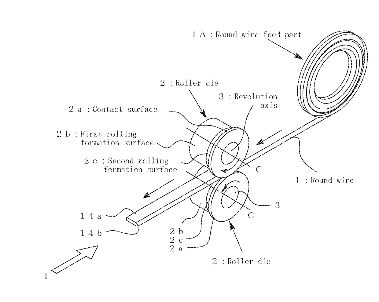
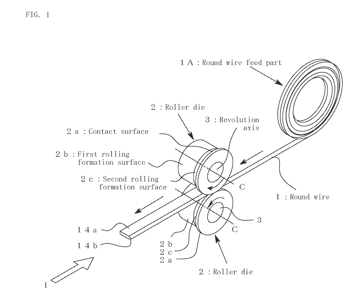
[0039]FIG. 1 is an explanation diagram of a principal part of a roller die device used in a method for molding a linear cutter of the present invention.

[0040]The roller die device includes: a pair of roller dies 2 and 2 arranged opposite to each other; a round wire feed part 1A in which a round wire 1 having a cross section of circular shape and serving as a wire rod is wound; and a guide (not shown) for guiding the round wire 1 fed from the round wire feed part 1A, to a position between the roller dies 2 and 2.

[0041]The roller dies 2 and 2 respectively include: contact surfaces 2a and 2a in contact with each other; first rolling formation surfaces 2b and 2b respectively formed at positions retracted from the contact surfaces 2a and 2a and formed in parallel to the revolution axes C and C of the roller dies 2 and 2; and inclined second rolling formation surfaces 2c and 2...


PUM

PropertyMeasurementUnit
Lengthaaaaaaaaaa
Angleaaaaaaaaaa
Deformation enthalpyaaaaaaaaaa

Abstract

A method for manufacturing a linear cutter permits continuous manufacturing of linear cutters and achieving remarkable reduction in processing steps, processing time, and a process cost, and is immediately feasible to linear cutters having special lengths. The method includes the steps of: preparing a pair of roller dies for forming a die hole for processing a wire rod into a predetermined shape, the die hole having keen angle parts for forming a cutting edge; and causing the wire rod to pass through the die hole in a state that the roller dies revolve and thereby forming a sectional shape of the wire rod into a pre-set shape and, at the same time, forming a cutting edge at least at one edge of the wire rod.

Description

TECHNICAL FIELD[0001]The present invention relates to: a method for manufacturing a linear cutter in which a cutting edge is formed at least at one edge of a body formed in a linear shape; and a roller die device used in this method.BACKGROUND ART[0002]For example, in manufacturing of an interior material for automobiles formed by bonding a substrate and a surface material together, the substrate and the surface material are pressure-bonded and joined together between an upper and a lower die and, at the same time, the surface material is cut by a heat cutting blade (for example, see numeral 6 in the figure of Patent Document 1). Such a heat cutting blade is a kind of linear cutter and, as shown in FIG. 4, includes: a linear body 14a cut in advance into a predetermined length in accordance with a usage situation or the like of the heat cutting blade 14 like the shape, the size, or the like of an object material to be cut; and a cutting edge 14b formed at least at one edge of the bod...

Claims


Application Information

Patent Timeline
IPC IPC(8): B21B1/16B21F45/00B21H7/10B21H8/00
CPCB21B1/166B21F45/00B21H7/10B21H8/00B26D1/04B26D7/10B26D1/0006
Inventor YAMAUCHI, RYUJI
Owner YAMAUCHI MATEX CORP
Why Eureka
Try Eureka