Systems, methods and devices that facilitate mechanical sinus dilation
- Summary
- Abstract
- Description
- Claims
- Application Information
AI Technical Summary
Benefits of technology
Problems solved by technology
Method used
Image

Examples
Embodiment Construction
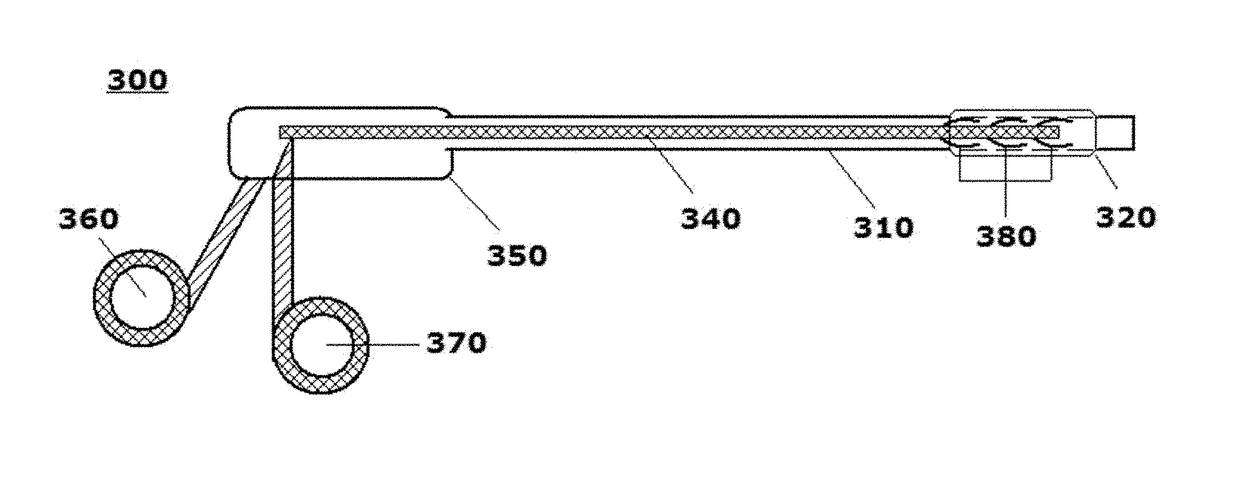
[0002]This disclosure is directed to a uniquely reusable system and / or apparatus for facilitating mechanical sinus ostial dilation or eustachian tube dilation in a medical setting with a device that is formed of all sterilizable constituent components.
2. Related Art
[0003]The paranasal sinuses are spaces in the facial skeleton above, below, between, and behind the eyes, which are normally filled with air and are connected to the nasal cavity. These sinuses continually produce mucus, which drains into the nasal cavity through small passageways called ostia. These ostia also allow the free flow of air between the nose and sinuses. Both ventilation and unrestricted mucus drainage are critical for sinus health. Sinusitis refers generally to a class of medical conditions involving inflammation of the sinus cavities and sinus openings within the nose. Sinusitis is generally categorized according to the length of time the conditions are present and how often the conditions recur.
[0004]Acute...
PUM
 Abstract
Description
Claims
Application Information
 - R&D
- Intellectual Property
- Life Sciences
- Materials
- Tech Scout
- Unparalleled Data Quality
- Higher Quality Content
- 60% Fewer Hallucinations
Browse by: Latest US Patents, China's latest patents, Technical Efficacy Thesaurus, Application Domain, Technology Topic, Popular Technical Reports.
© 2025 PatSnap. All rights reserved.Legal|Privacy policy|Modern Slavery Act Transparency Statement|Sitemap|About US| Contact US: help@patsnap.com