Robotic gardening device and method for controlling the same

a robot and gardening technology, applied in the direction of process and machine control, image enhancement, instruments, etc., can solve the problem that one cannot rely on human safety, and achieve the effect of very precise object detection

Active Publication Date: 2018-03-22
HONDA RES INST EUROPE
View PDF21 Cites 26 Cited by
  • Summary
  • Abstract
  • Description
  • Claims
  • Application Information

AI Technical Summary

Benefits of technology

[0016]It is furthermore advantageous that the computing unit comprises a classifier using deep learning and / or HOG features and / or optical flow and / or stereo camera depth data for determining an obstacle as a human or an animal. As mentioned above, the HOG features have proven to be very robust and in particular these features are well known for detecting pedestrians that walk into a driving path of a vehicle. Thus, algorithms that are known from warning systems or emergency braking systems of vehicles like cars may be adapted for distinguishing life forms such as humans from static obstacles. Techniques like optical flow are also very useful to identify life forms and distinguish from static obstacles. In combination with map data it is possible to calculate an optical flow that is caused by the motion of the autonomous lawn mower of static obstacles and compare it to an optical flow of other obstacles that are not known from the map. These other obstacles rather likely are not static and will thus change their position. Thus, since often static elements or obstacles are included in map data, map data is helpful to distinguish between non-static and static objects. On the other side, an artificial neural network may be used for deep learning which shows that object detection can be very precise. This technique is thus also very suitable for detecting and distinguishing different life forms. It is to be noted that in this sense meaning “different life forms” does not only relate to distinguishing between animals and human beings, but also between children and adults.

Problems solved by technology

Hence, one cannot rely human safety on the fact that actually they should leave the field of operation when the robotic gardening device is active.
For example, an animal that is determined as an obstacle could possibly be scared and thus be motivated to leave the garden.

Method used


Image

  • Robotic gardening device and method for controlling the same
  • Robotic gardening device and method for controlling the same
  • Robotic gardening device and method for controlling the same

Examples


Embodiment Construction

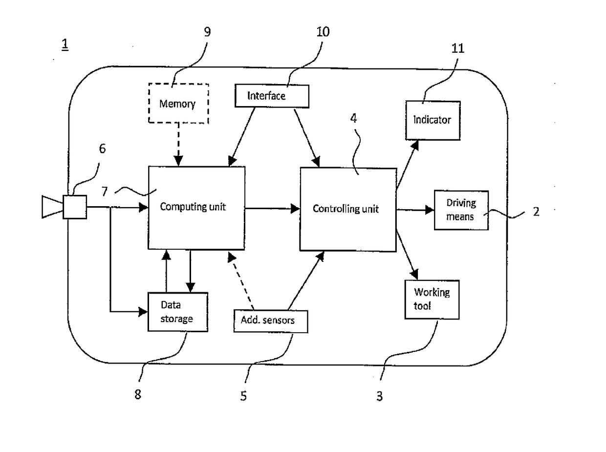
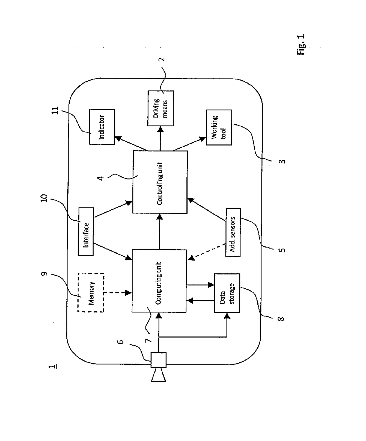
[0022]In FIG. 1 a schematic of an autonomous lawn mower 1 as one example for a robotic gardening device is shown. The autonomous lawn mower 1 in a known manner comprises a driving means 2 and a working tool 3. The driving means 2 comprises a drive motor that is mechanically connected to drive wheels in order to propel the vehicle. It is to be noted that further parts of the entire driving mechanism that are well known in the art are not shown in the schematic. This is for example an energy storage like an accumulator or the like.

[0023]The working tool 3 comprises a further drive motor for driving blades on the lower side of the autonomous lawn mower 1 for cutting grass. Working tool 3 and driving means 2 both are controlled by a controlling unit 4 which is for example a data processing unit like a controller that supplies the driving means 2 and the working tool 3 with respective drive signals. Working tool 3 is controlled for activating a deactivating rotation of the blades whereas...


PUM


Abstract

The invention regards a robotic gardening device comprising driving means for propelling the robotic gardening device, a working tool for performing dedicated gardening work and a controlling unit for controlling said driving means and the working tool and a method for controlling the same. The robotic gardening device further comprises at least one environment sensor generating a signal indicative of objects in the environment of the robotic gardening device, a computing unit for classifying these objects, wherein the classes comprise at least two different classes for objects being determined to be humans. The computing unit is configured to control the driving means and/or the working device according to a predetermined behavior associated with the respective objects class.

Description

BACKGROUNDField[0001]The invention regards a robotic gardening device such as an autonomous lawn mower or an autonomous scarifier and a method for controlling the same in particular its behavior in response to detection of different types of obstacles.Description of the Related Art[0002]The market for autonomous gardening devices such as autonomous lawn mowers or the like is increasing year by year. Robotic gardening devices increase comfort of the user drastically and thus become more and more popular. Since such mowers or scarifiers move autonomously without human supervision, safety is an important aspect during operation. Up to now, lawn mowers or scarifiers only have basic safety functions implemented such as bump sensors installed at the front side of the device. If the autonomous gardening device contacts an obstacle in the driving path, the autonomous gardening device will automatically change its driving direction and thus move away from the obstacle. In order to ensure saf...

Claims


Application Information

Patent Timeline
Patent Type & Authority Applications(United States)
IPC IPC(8): A01D34/00
CPCA01D34/008G05D2201/0208G06N99/005G06K9/6212G06T7/20G06T7/75G06T2207/20081A01D75/185G05D1/0246G06V40/10G06V20/10G06N20/00B60W30/00
Inventor EINECKE, NILSFRANZIUS, MATHIAS
Owner HONDA RES INST EUROPE
Why Eureka
Try Eureka