
Particle beam therapy system and method for updating particle beam therapy system

Active Publication Date: 2018-03-08
HITACHI LTD
View PDF5 Cites 4 Cited by
  • Summary
  • Abstract
  • Description
  • Claims
  • Application Information

AI Technical Summary

Benefits of technology

The present invention allows for adding a treatment room with minimal impact on an existing system. Additionally, it provides an update method that allows for additional installation, adjustment, and testing of a new system during periods when no treatment is given in the existing system.

Problems solved by technology

A particle beam therapy system needs to make highly accurate beam position adjustment to introduce the ion beam into the affected part, and takes a great deal of time for the adjustment and testing.
However, it takes time to adjust and test the system at a time of update and a suspension period of treatment is prolonged.
During that period, patients cannot get treatment, it is difficult to maintain installation and maintain employees, and other disadvantages occur.

Method used


Image

  • Particle beam therapy system and method for updating particle beam therapy system
  • Particle beam therapy system and method for updating particle beam therapy system
  • Particle beam therapy system and method for updating particle beam therapy system

Examples


first embodiment

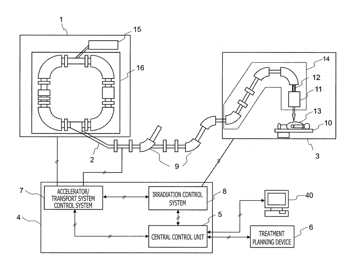
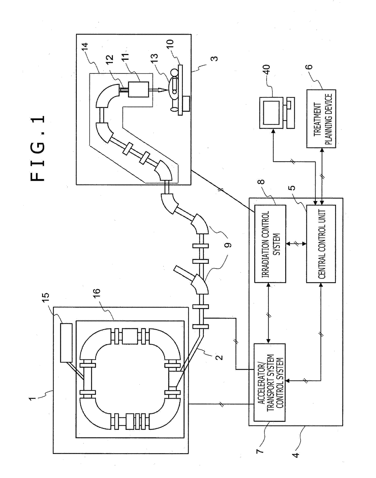
[0045]In the present embodiment, as shown in FIG. 3(A), a treatment system that includes one circular accelerator 16a and two treatment rooms is assumed as an existing treatment system, and a procedure described below is executed in respect to update of installation related to each treatment room and a control system. It is noted that the treatment system will be described as a typical example since the number of treatment rooms, arrangement, and the like vary with installation. Furthermore, the procedure is illustrated in FIG. 10.

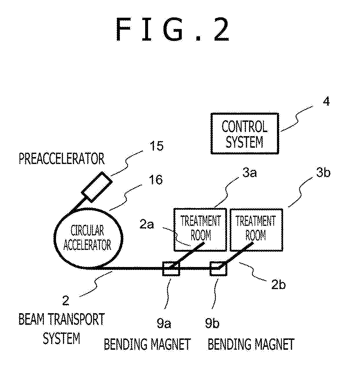
[0046]As shown in FIG. 3(A), the existing treatment system includes a preaccelerator 15a, a circular accelerator 16a, beam transport systems 2a and 2b, bending magnets 9a and 9b, and treatment rooms A and B. The charged particle beam accelerated to have desired energy by the circular accelerator 16a is transported to a beam irradiation device 3a in the desired treatment room A or a beam irradiation device 3b provided in the desired treatment room B by swit...

second embodiment

[0068]In the present embodiment, as shown in FIG. 5(A), a treatment system that includes one circular accelerator and two treatment rooms is assumed as an existing treatment, and a procedure described below is executed in respect to update of installation related to the accelerators and the control system. It is noted that the treatment system will be described as a typical example since the number of treatment rooms, arrangement, and the like vary with installation.

[0069]In respect to an example of the existing system of FIG. 5(A), a new preaccelerator 15b, a new circular accelerator 16b, and a new bending magnet 9d are installed, a branch is provided in the existing beam transport system 2, and a beam transport system 2d that connects the circular accelerator 16b to the branch portion of the beam transport system 2 so that the beam can be transported into the existing treatment rooms as shown in FIG. 5(B). At this time, the bending magnet 9d is installed in a linear section of the...


PUM


Abstract

A system update method for a particle beam therapy system, includes: a step of providing a new beam transport system in such a manner as to be branched off from an existing beam transport system of the particle beam therapy system; and a step of providing new installation connected to the new beam transport system, in which the branch is provided in a linear section of the existing beam transport system.

Description

TECHNICAL FIELD[0001]The present invention relates to a particle beam therapy system that makes use of a charged particle beam (an ion beam) of protons, heavy ions or the like, and that is suitable when a new system is introduced or a system is updated while a particle beam treatment is continued.BACKGROUND ART[0002]There is known a particle beam treatment for irradiating a patient's cancer affected part with an ion beam of protons, heavy ions or the like as a radiation treatment for cancer. A particle beam therapy system needs to make highly accurate beam position adjustment to introduce the ion beam into the affected part, and takes a great deal of time for the adjustment and testing. Patent Documents 1 and 2 describe the adjustment and the testing of the particle beam therapy system.[0003]If the need to update an existing system to a new system in the same site arises due to aging of the existing system, application of improvement following technological advancement, such a flow ...

Claims


Application Information

Patent Timeline
IPC IPC(8): A61N5/10
CPCA61N5/1077A61N5/1043A61N5/1075A61N2005/1087A61N5/1079
Inventor HORI, YOSHIHITOMATSUSHITA, TAKAYOSHITOBINAGA, KOUJI
Owner HITACHI LTD
Learn More