
Device to reduce traumatic brain injury

Inactive Publication Date: 2018-02-01
HUANG CHIMING
View PDF75 Cites 15 Cited by
  • Summary
  • Abstract
  • Description
  • Claims
  • Application Information

AI Technical Summary

Benefits of technology

The present invention solves the problem of traumatic brain injury caused by head impacts by identifying a dynamic concussion threshold that is individualized to the user through machine-learning of their non-injurious head movement parameters. The technology uses sensors placed on the user's head and body to measure acceleration and position to analyze the user's biomechanical properties in three dimensions. This data is then stored and used to predict potential concussions and provide protection to the user in real-time through head gear or body wear that dissipates the impact force and energy. The system also considers the user's neck stiffness to render the most protection when the neck is least stiff. Overall, the invention provides a personalized approach to preventing traumatic brain injury by identifying and protecting against potential concussions.

Problems solved by technology

High positive acceleration or negative acceleration may cause the brain to contact the skull with enough force to cause brain injury.
These gradients can bring about dramatic disruptions in neuronal metabolism and function at the cellular level without obvious or noticeable macroscopic movement of the brain.
. . (such head-impact-measurement devices) did not have the requisite sensitivity (for) .
. . concussion. . . . (Such) head-impact-monitoring systems have limited clinical utility due to error rates, designs, and low specificity in predicting concussive injury.” This conclusion largely mirrors a series of studies earlier, indicating that data from the HITS lacked sensitivity and specificity and can predict concussion only with a 56% success rate, barely better than coin-toss (these series of studies are cited in the O'Conner et al review).
At least one drawback to the approach of sensing head impact in much of the prior art is that the threshold for concussion may be different for different people.
Another drawback is that the threshold for concussion for the same person may be different for different directionalities of the impact force.
Or it may be short, spanning over a matter of minutes or days as it is now known that a person is likely to be more vulnerable to a second concussion immediately after a concussion.
The matter of time over seconds or less is therefore relevant as the consequences of a head impact event can be disastrous especially when the impact occurs while the person does not know, is not prepared, or is otherwise unaware of the impending impact.
All of these factors render it impractical to adopt a certain, one-size-fits-all constant value as a threshold beyond which a concussion may occur or as a threshold beyond which some form of protective countermeasure should be launched.
Therefore, another drawback to the current approach is that sensors in many prior arts do not provide any information or data to help track and subsequently manage harmful, sub-concussive impact events.
Another drawback to the current approach is that sensors in many prior arts are programmed with an emphasis to sample the peak amplitudes of the impact force / energy, typically requiring more than 10-20 ms to manifest.
Many of the current approach of sensing impact force / energy do not consider the essence of speed and may be therefore too slow to be incorporated in a device designed for launching an effective countermeasure to prevent a concussion before such a concussion or related brain injuries can take effect.

Method used


Image

  • Device to reduce traumatic brain injury
  • Device to reduce traumatic brain injury
  • Device to reduce traumatic brain injury

Examples


Embodiment Construction

[0034]The following detailed description of the invention references the accompanying drawings that illustrate specific embodiments in which the invention can be practiced. The embodiments are intended to describe aspects of the invention in sufficient detail to enable those skilled in the art to practice the invention. Other embodiments can be utilized and changes can be made without departing from the scope of the present invention. The following detailed description is, therefore, not to be taken in a limiting sense. The scope of the present invention is defined only by the appended claims, along with the full scope of equivalents to which such claims are entitled.

[0035]In this description, references to “one embodiment”, “an embodiment”, or “embodiments” mean that the feature or features being referred to are included in at least one embodiment of the technology. Separate references to “one embodiment”, “an embodiment”, or “embodiments” in this description do not necessarily ref...


PUM


Abstract

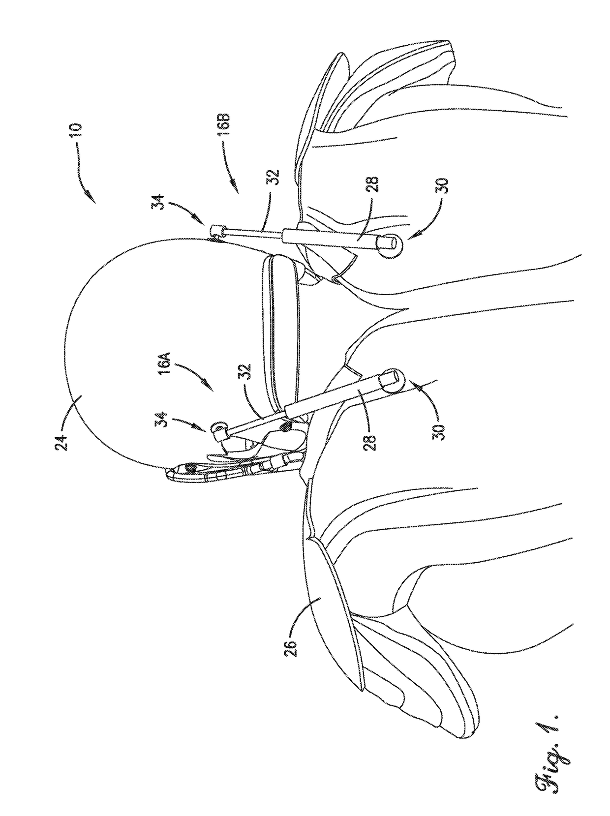
A device for reducing traumatic brain injury comprises a first sensor, a first linkage element, and a processing element. The first sensor is coupled to a head component and configured to measure an acceleration of a user's head and to generate a sequence of real-time measured samples. The first linkage element is configured to connect the head component to a body component and is able to switch between a first state in which it is relatively flexible and a second state in which it is relatively rigid. The first linkage element is switched from its first state to its second state by a locking signal. The processing element is configured to receive the real-time measured samples and to generate the locking signal when each of a portion of the real-time measured samples is greater than one of a corresponding portion of a plurality of dynamic concussion thresholds.

Description

RELATED APPLICATIONS[0001]The current patent application is a continuation-in-part patent application which claims priority benefit with regard to all common subject matter to U.S. patent application Ser. No. 14 / 959,083, titled “DEVICE TO REDUCE TRAUMATIC BRAIN INJURY”, and filed Dec. 4, 2015, that is a non-provisional patent application which claims priority benefit with regard to all common subject matter to U.S. Provisional Patent Application Ser. No. 62 / 088,181, titled “DEVICE, SYSTEM, AND METHOD TO REDUCE TRAUMATIC BRAIN INJURY: THE SENSOR STAGE”, filed Dec. 5, 2014. Both previously-filed applications are hereby incorporated by reference in their entireties into the current patent application.BACKGROUND OF THE INVENTIONField of the Invention[0002]Embodiments of the current invention relate to devices configured to reduce traumatic brain injury.Description of the Related Art[0003]Closed-head traumatic brain injury (TBI) is typically a result of the brain impacting the interior o...

Claims


Application Information

Patent Timeline
IPC IPC(8): A61B5/05A61B5/055A63B71/10A61B5/11A61B5/375
CPCA61B5/05A61B5/1107A61B5/055A63B71/10A61B5/0482F41H1/04A42B3/0473A61B5/7282A61B5/11A61F5/3707A61B5/1123A61B5/375
Inventor HUANG, CHIMING
Owner HUANG CHIMING
Learn More