Gas injection blower

Active Publication Date: 2018-01-18
ORIENT SERVICE
View PDF7 Cites 0 Cited by
  • Summary
  • Abstract
  • Description
  • Claims
  • Application Information

AI Technical Summary

Benefits of technology

The present invention aims to solve the problem of easy accommodation of dust or dirt in the depressurization slot of a traditional blower pump chamber and improve the corrosion caused by acid or alkaline dirt during transportation of the semiconductor manufacturing process waste gas. The invention provides a gas injection blower with a device housing and fan blade made from a corrosion resistance plastic material. The invention can regularly supply the descaling gas to the depressurization slot and reduce the amount or times of maintenance or repairs of the washable blower and extend the life of the blower. Nitrogen can be used as the descaling gas as it will not easily chemically react with acidic or alkaline chemicals and can effectively dilute acid or alkali concentration.

Problems solved by technology

Because the different types of gas are transported by the blower, particularly when the gas is a gas having an acidic or alkaline or corrosive property, the accumulated dust or dirt accumulated in the depressurization slot have corrosive or toxic property to affect the service life of the blades, the drive shaft, the pump chamber walls and other components.
The acidic alkaline dust, dirt or water mist generated in the water washing of the process exhaust gases will be easily accumulated in the pump chamber of the blower, especially in the depressurization slot of the pump chamber, resulting in corrosion of the blades, the drive shaft, the pump chamber walls and other components, and even affect the life of the blower.

Method used


Image

  • Gas injection blower
  • Gas injection blower
  • Gas injection blower

Examples


Embodiment Construction

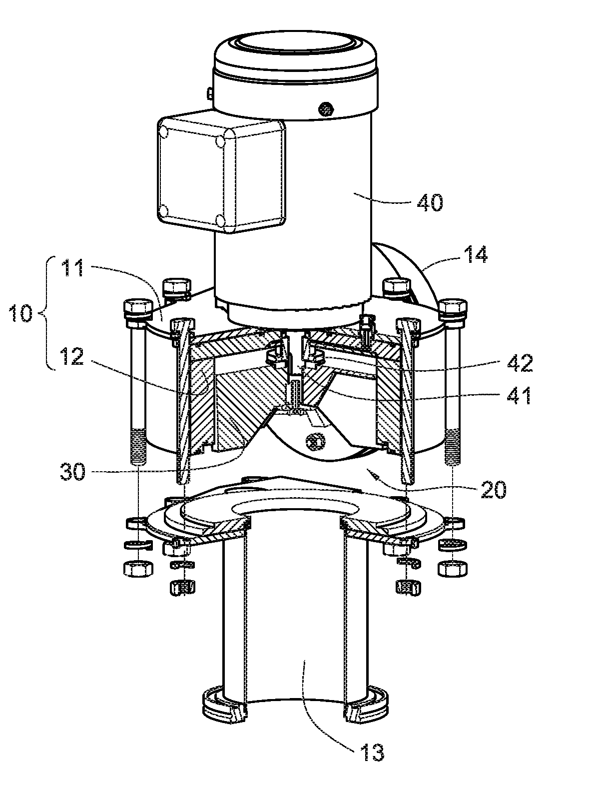
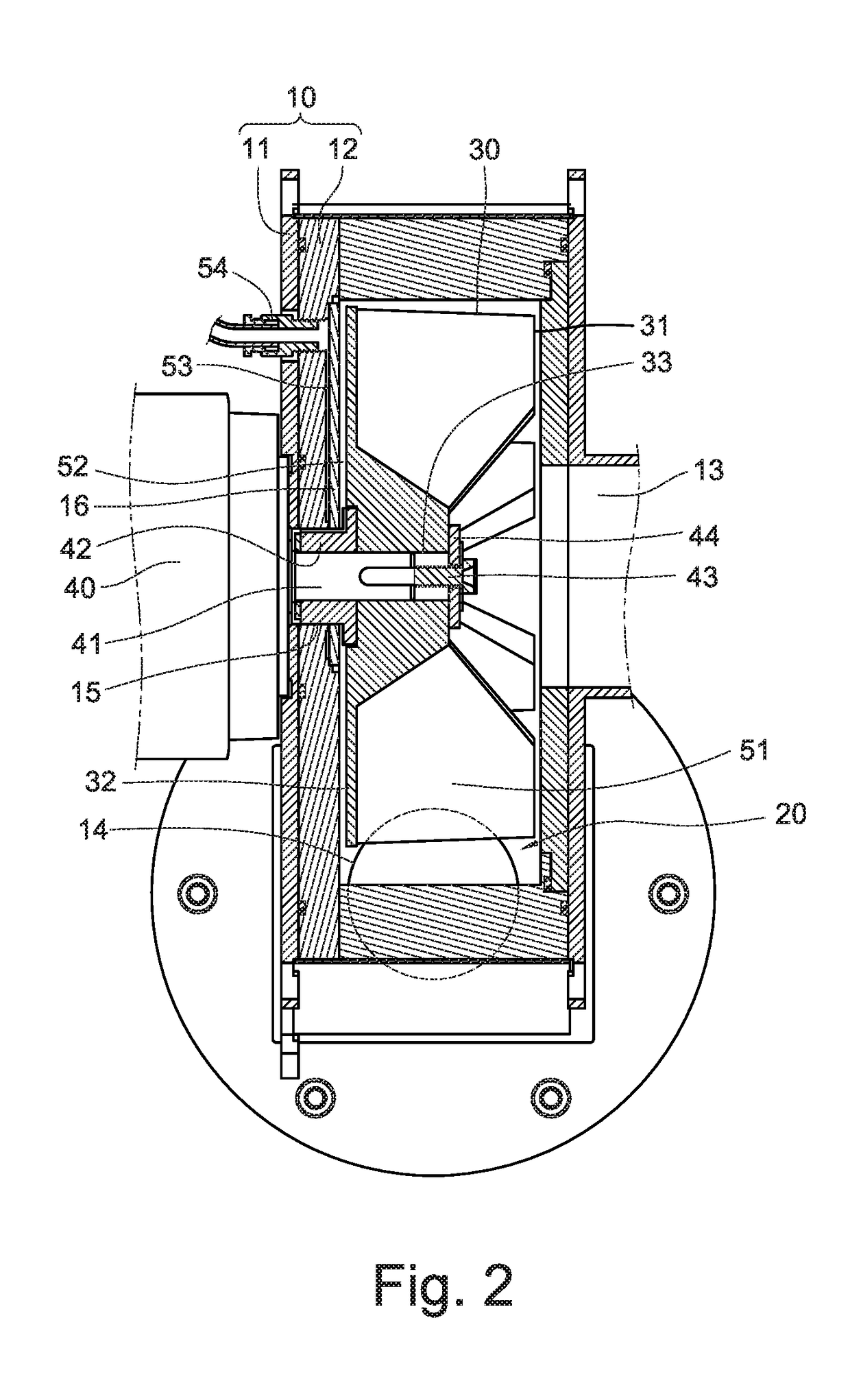
[0032]Firstly, please refer to the FIGS. 1 to 3 illustrating a preferred embodiment of the present invention, the gas injection blower of the present invention comprises a device housing 10 and a fan blade 30.

[0033]The device housing 10 has a cylindrical pump chamber 20 formed inside the device housing 10. At the perimeter of the device housing 10, an air inlet 13, an air discharge aperture 14 and a shaft hole 15 for fluidly connecting to a pump chamber 20 are formed. The device housing 10 includes an outer housing 11 and an inner housing 12. The outer housing 11 is made of stainless steel, and the inner housing 12 is made of acid and alkali erosion-resistant plastic material. In addition to increasing structure intensity of the device housing 10, the vulnerable acid or alkali erosion problem of the device housing 10 is improved.

[0034]The fan blade 30 is disposed in the pump chamber 20. The fan blade 30 is made of acid and alkali erosion-resistant plastic material. The fan blade 30 ...


PUM


Abstract

A gas injection blower includes a housing forming a box around the pump chamber, wherein the perimeter of the housing is also formed with a pump chamber communicating air inlet and an exhaust outlet, a fan shaft connected to a drive shaft the form of a rotatable type arranged in the pump chamber, the air inlet, forming a pressurized chamber of the pump flow passage between the fan and air vents and communicate with each other, the drive shaft extending through the shaft connected to a pump outdoor power source, wherein the drive shaft, at least between the inner wall of the frame around the blades and the pump chamber is formed a slit communicating the boost pressure drop of the flow channel, which is housing and forming a gap communicating the pressure drop gas injection passage; with the passage of gas injected into the inner injection cleaning gas pressure, to improve the traditional drop relatively easy accumulation of dust inside the gap problem.

Description

TECHNICAL FIELD[0001]The present invention relates to a structure of a blower, particularly to a gas injection blower.BACKGROUND OF THE INVENTION[0002]The blower is an equipment which uses fan blades of a pump chamber of a motor-driven pump to rotate, thereby generating a suction airflow. In general, the blower has been widely used in a gas blowing equipment or a gas suction equipment to produce a forced convection gas flow.[0003]Furthermore, a pump chamber of the blower is formed by a device housing. The device housing has an air inlet and an air discharge aperture. By the blower motor attached to blower (or the so-called motor) or an external power source, fan blades are driven in the pump chamber to rotate to force the outside atmosphere air move in from the air inlet or to drive the gas in an air extraction equipment to move into the pump chamber, and through the operation of the fan blades the air in the pump chamber will be pushed to the air discharge aperture and be discharge...

Claims


Application Information

Patent Timeline
IPC IPC(8): F04D29/42F04D29/28F04D29/053F04D29/70F04D29/02
CPCF04D29/4206F04D29/281F04D29/701F04D29/023F04D29/053F04D29/4226F04D29/705F04D7/06
Inventor FONG, WU-YULIOU, ZIH-CIJHANG, JHIH-HAO
Owner ORIENT SERVICE
Why Eureka
Try Eureka