
Radar level gauge system with single propagation mode feed-through

a technology of propagation mode and radar level gauge, which is applied in the direction of transmission system, liquid/fluent solid measurement, reradiation, etc., can solve the problems of flammability of products to be monitored and/or measured, and achieve the effect of reducing the risk of unwanted materials and strong attenuation of microwave signals

Active Publication Date: 2018-01-11
ROSEMOUNT TANK RADAR
View PDF5 Cites 10 Cited by
  • Summary
  • Abstract
  • Description
  • Claims
  • Application Information

AI Technical Summary

Benefits of technology

The present invention meets the requirements for flameproofing and provides a way to transmit signals through a feed-through with low signal loss caused by reflection. This improves the performance of radar level gauges, particularly in detecting weak echoes. The invention reduces unwanted reflections by using a gradual transition of the effective impedance seen by the microwaves traveling through the feed-through. To further increase the bandwidth for which single mode propagation can be achieved, a mode filter can be used to suppress propagation in other modes than the single propagation mode. To ensure a direct abutment between the impedance matching members and the ends of the dielectric plug, the impedance matching members can be pressed against the ends of the dielectric plug. To provide a single seal between the electronic devices of the radar level gauge system and the tank, a first weld can be used to connect the first hollow conductor section to the second hollow conductor section, and a second weld can be used to connect the second hollow conductor section to the third hollow conductor section.

Problems solved by technology

Since products to be monitored and / or measured are often flammable, special safety requirements exist for equipment, such as radar level gauge systems or at least parts thereof that are positioned within a so-called hazardous area.

Method used


Image

  • Radar level gauge system with single propagation mode feed-through
  • Radar level gauge system with single propagation mode feed-through
  • Radar level gauge system with single propagation mode feed-through

Examples


Embodiment Construction

[0065]In the present detailed description, various embodiments of the radar level gauge system according to the present invention are mainly discussed with reference to a battery-powered radar level gauge system with wireless communication capabilities.

[0066]It should be noted that this by no means limits the scope of the present invention, which equally well includes, for example, radar level gauge systems that are not included in a process management system or radar level gauge systems that are loop-powered or powered with dedicated power lines.

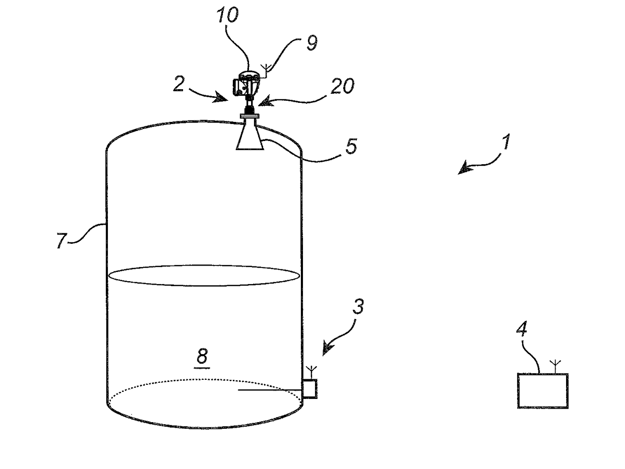
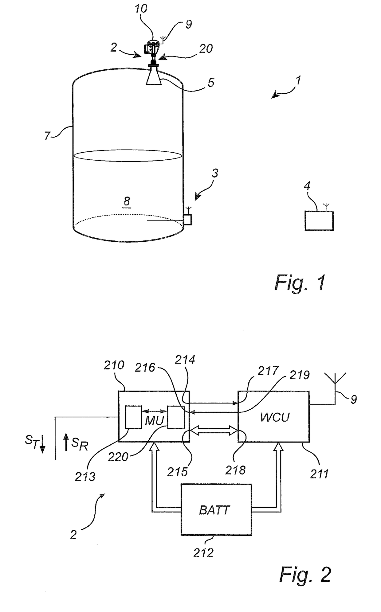
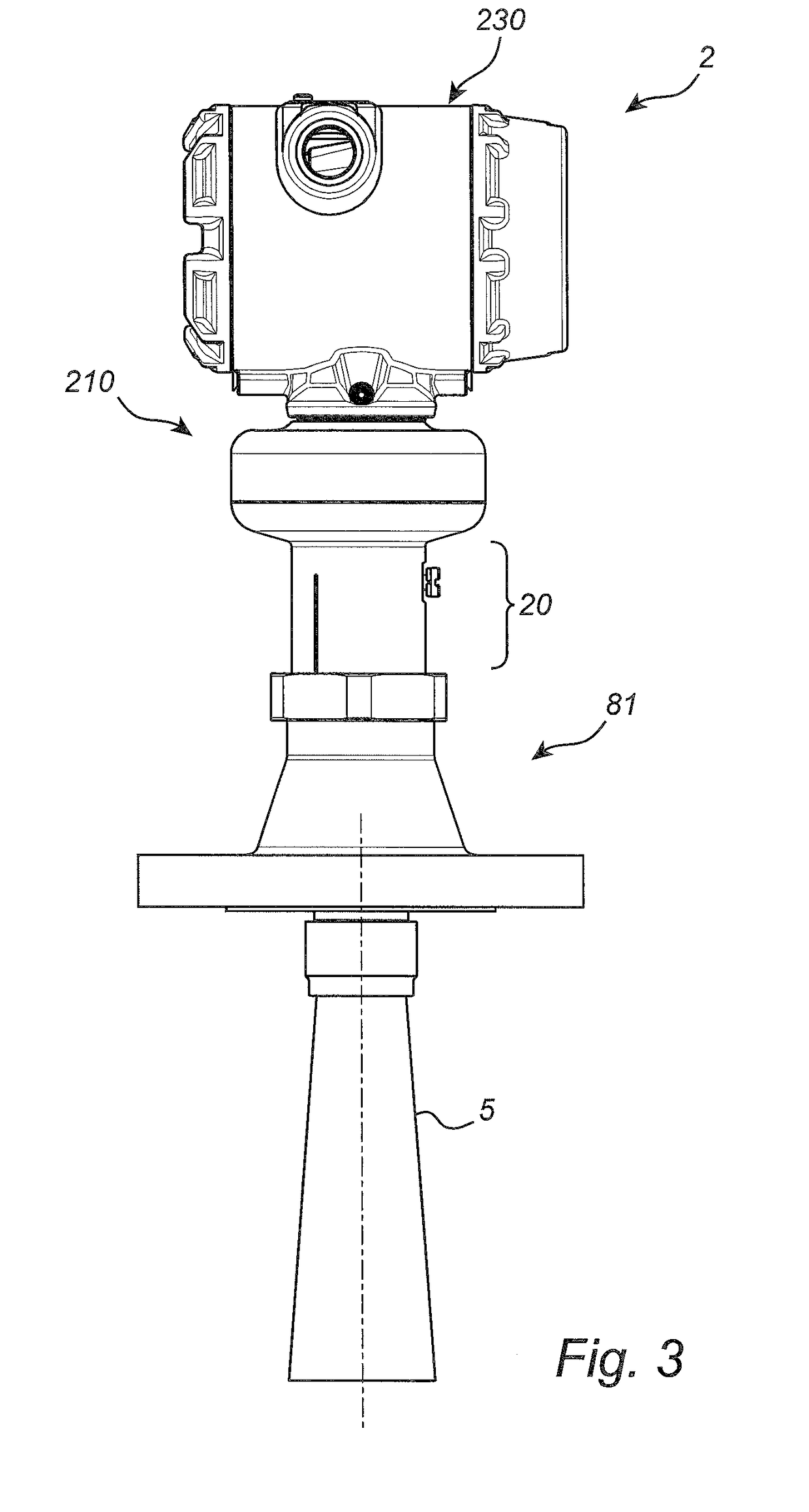
[0067]FIG. 1 schematically shows a process monitoring system 1 comprising a plurality of field devices, including an example embodiment of a radar level gauge system 2 and a temperature sensing device 3 wirelessly connected to a host system 4. The radar level gauge system 2 comprises a measurement electronics unit 10 arranged outside the tank 7, an antenna 5 arranged inside the tank 7, and a feed-through 20 connecting the measurement electr...


PUM


Abstract

A radar level gauge system, comprising a transceiver; an antenna; a feed-through connecting the transceiver and the antenna; and processing circuitry coupled to the transceiver. The feed-through comprises a first waveguide section comprising a dielectric plug sealingly arranged in a cylindrical first hollow conductor section having a diameter selected for single mode propagation; a second waveguide section arranged between the transceiver and the first waveguide section and comprising a cylindrical second hollow conductor section having a second diameter selected for single mode propagation, a third waveguide section arranged between the antenna and the first waveguide section comprising a cylindrical third hollow conductor section having a third diameter selected for single mode propagation; a first impedance matching waveguide section arranged between the first waveguide section and the second waveguide section, and a second impedance matching waveguide section arranged between the first waveguide section and the third waveguide section.

Description

TECHNICAL FIELD OF THE INVENTION[0001]The present invention relates to a radar level gauge system and to a method of manufacturing a feed-through for a radar level gauge system.TECHNICAL BACKGROUND[0002]Radar level gauge (RLG) systems are in wide use for determining the filling level of a product contained in a tank. Radar level gauging is generally performed either by means of non-contact measurement, whereby electromagnetic signals are radiated towards the product contained in the tank, or by means of contact measurement, often referred to as guided wave radar (GWR), whereby electromagnetic signals are guided towards and into the product by a transmission line probe acting as a waveguide. The probe is generally arranged to extend vertically from the top towards the bottom of the tank.[0003]An electromagnetic transmit signal is generated by a transceiver and propagated towards the surface of the product in the tank, and an electromagnetic reflection signal resulting from reflection...

Claims


Application Information

Patent Timeline
IPC IPC(8): G01F23/284
CPCG01F23/284G01S7/03G01S13/88H01P5/024H01P5/103H01Q13/02G08C17/02
Inventor OHLSSON, MAGNUSELMBERG, PETER
Owner ROSEMOUNT TANK RADAR
Learn More