
Method for measuring quick changes in low surface conductivity of dielectrics under electromagnetic interference of line voltage and equipment to perform this type of measurement

a dielectric and electromagnetic interference technology, applied in the direction of measuring interference from external sources, measuring devices, instruments, etc., can solve the problems of signal jitter, surface conductivity measurement, slowing down the response of measuring equipment,

Inactive Publication Date: 2018-01-04
PALACKY UNIV OLOMOUC
View PDF1 Cites 6 Cited by
  • Summary
  • Abstract
  • Description
  • Claims
  • Application Information

AI Technical Summary

Benefits of technology

The patent describes a device that measures changes in the conductivity of materials caused by electromagnetic interference. The device uses a special sensor to measure these changes and a logic block to control the generation of pulses. The pulses are then sent to a voltage divider surface/resistor, which then sends a signal to sample-and-hold amplifiers. The sample-and-hold amplifiers control the sampling of the signal and send it to a differential amplifier. The differential amplifier filters out unwanted fluctuations in the signal and sends it to the equipment being tested. The device can be connected to a resistor or a transformer for measuring electromagnetic interference. The technical effect of this device is to provide a reliable and accurate measure of changes in conductivity caused by electromagnetic interference.

Problems solved by technology

The technical problem addressed in this patent text is the effect of electromagnetic interference (EMI) on the measurement of surface conductivity using a voltage divider. The interference can cause signal jitter, making it difficult to measure the conductivity of low-conductivity materials. The solution proposed is to use a lock-in amplifier for signal modulation to reduce the noise level in the background.

Method used


Image

  • Method for measuring quick changes in low surface conductivity of dielectrics under electromagnetic interference of line voltage and equipment to perform this type of measurement
  • Method for measuring quick changes in low surface conductivity of dielectrics under electromagnetic interference of line voltage and equipment to perform this type of measurement
  • Method for measuring quick changes in low surface conductivity of dielectrics under electromagnetic interference of line voltage and equipment to perform this type of measurement

Examples


Embodiment Construction

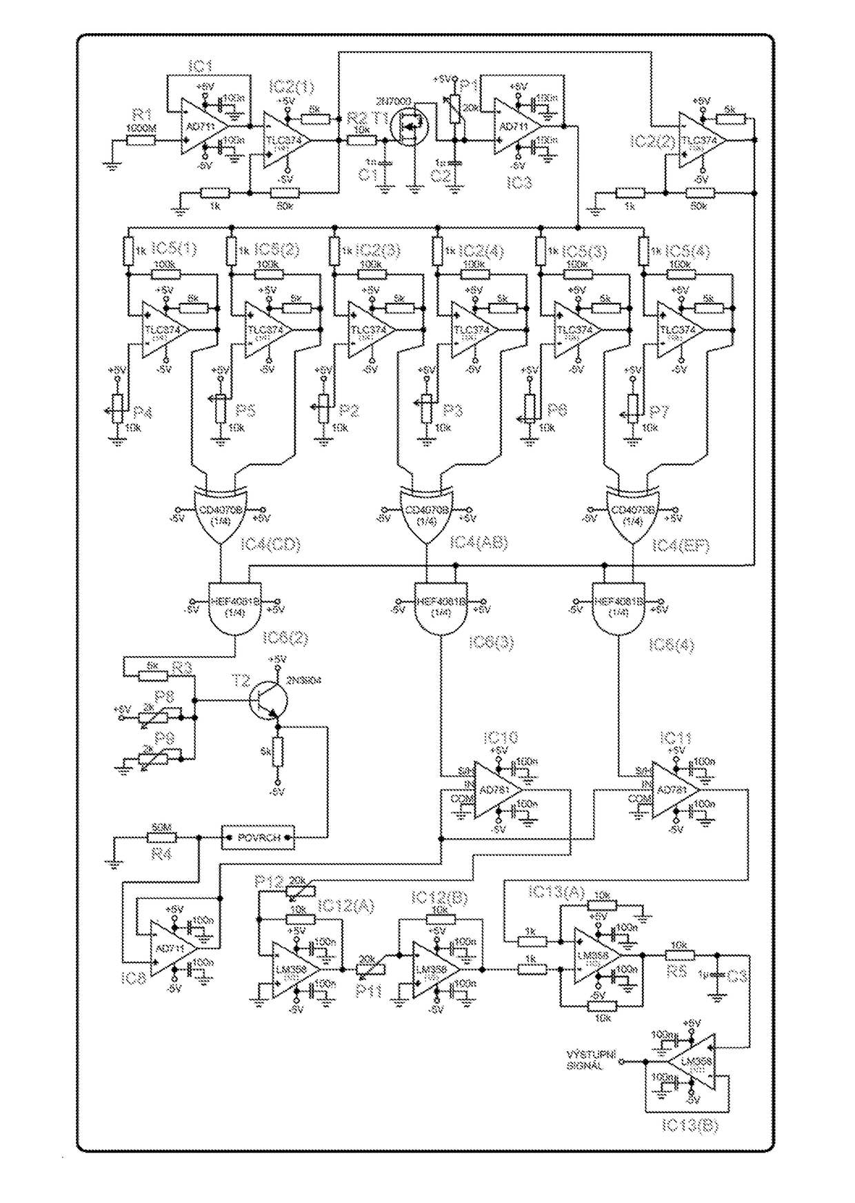
[0033]The solution suggested will be described in activity and function of the equipment for measurement of quick changes of low surface conductivity of dielectrics under electromagnetic interference of line voltage based on the method to measure quick changes of low surface conductivity of dielectrics the electrical diagram of which using specific electrical components from the current parts supply offered in the market is presented in FIG. 5 and which was successfully tested under operational conditions.

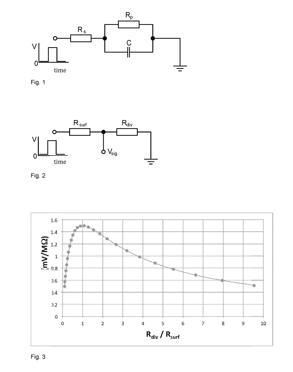
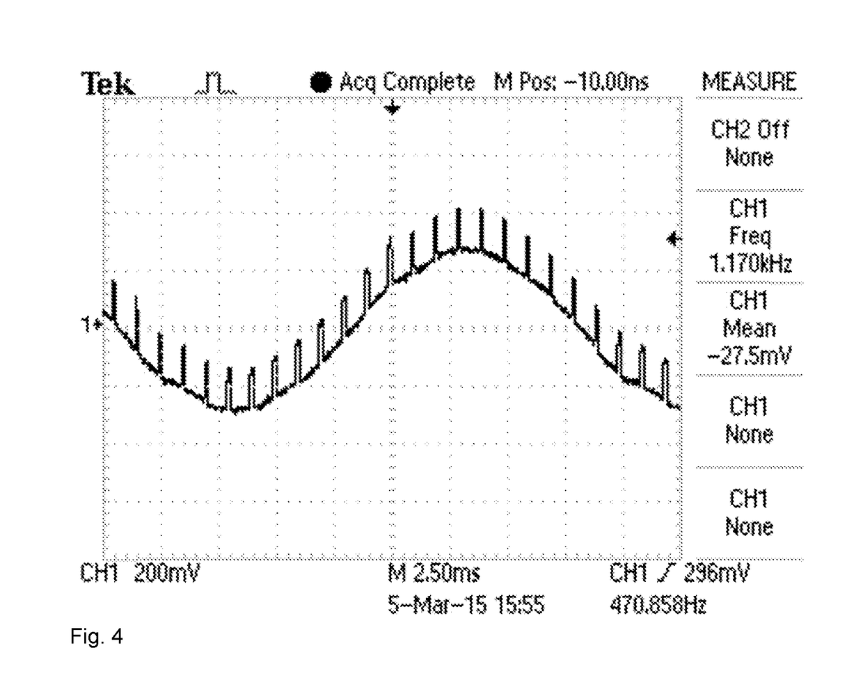
[0034]The equipment is based on a voltage divider and synchronisation of measuring pulses with periodical sinusoidal course of interference effects. A square pulse with duration 1 ms in each positive semi-period 60 Hz EMI is applied on the tested surface and the potential in the divider is sampled both immediately before application of the measuring pulse and just before its end. The difference between these two readings is acquired using a differential amplifier, and it is close t...


PUM


Abstract

The method for measuring of quick changes of low surface conductivity of dielectrics under electromagnetic interference of line voltage is based on a comparison measurement on a voltage divider and synchronisation of measuring pulses with periodic sinusoidal course of interference when voltage with pre-set parameters of square pulse is brought to the tested dielectric surface and potential is sampled in the voltage divider consisting of the measured dielectric surface and a resistor with preselected resistivity in certain time intervals both before application of the measuring pulse and immediately before its end, and then based on a difference between the values measured using a differential amplifier, the value corresponding to that measured without effect of electromagnetic interference 60 Hz is derived and the result is the possibility to measure quick changes of low surface conductivity of dielectric surface.
The equipment for measurement of quick changes of low surface conductivity of dielectrics under electromagnetic interference of line voltage contains the sensing element (1) monitoring electromagnetic interference and the block (2) monitoring electromagnetic interference that is connected to the sensing element, and the comparative block (3) for control of generation of time sequences is connected to the first output from the block (2) and the block (4) for generation of pulses is also connected to the first output from the block (2), and the output of the block (4) are square pulses 1 ms/±5 V, and the first output 10 μs/±5 V and the second output 10 μs/±5 V are connected to inputs of the block (6) of logic elements, and another output of the block (2) monitoring electromagnetic interference is connected to the comparative element (5), the output of which is connected to the fourth input of the block (6) of logic elements, and the first output of the bloc (6) of logic elements is connected through the block (7) for modulation of pulses to the with the output as pulse 0 to 300 mV to the tested surface in the block (8) of the voltage divider surface/divider-resistor where output from this block (8) of the voltage divider surface/resistor-divider is connected through the block (11) of the voltage follower to the divider with very high input impedance to signal inputs of the first sample-and-hold amplifier (9) and of the second sample-and-hold amplifier (10), and the second input for control of sampling of the first sample-and-hold amplifier (9) and the second input for control of sampling of the second sample-and-hold amplifier (10) are connected with corresponding outputs for control of sampling of the block (6) of logic elements, and output of the first sample-and-hold amplifier (9) is connected through the block (12) of two inverting amplifiers connected in series to inverting input of the differential amplifier (13), and output from the second sample-and-hold amplifier (10) is connected to its non-inverting input, and the differential amplifier (13) is connected through the block (14) to eliminate accidental jitter of signal and the output block (15) with low impedance to the output from the equipment.

Description


Claims


Application Information

Patent Timeline
Owner PALACKY UNIV OLOMOUC
Learn More