Shape evaluation method and shape evaluation apparatus

a technology of shape evaluation and evaluation method, which is applied in the direction of image enhancement, programme control, total factory control, etc., can solve the problems of not being able to determine whether the surface quality matches the evaluation of surface roughness, and the evaluation of surface quality is different from the desired design

Active Publication Date: 2017-12-28
MAKINO MILLING MASCH CO LTD
View PDF3 Cites 4 Cited by
  • Summary
  • Abstract
  • Description
  • Claims
  • Application Information

AI Technical Summary

Benefits of technology

The present invention provides a method and device to evaluate the quality of an object's surface based on its shape. This can help improve the manufacturing process of products that are visually felt by people.

Problems solved by technology

Alternatively, unwanted polygonal lines or the like may appear in the processed workpiece, which may be greatly different from the desired design.
On the contrary, although the surface roughness evaluation is out of the allowable range, the surface may look beautiful to the eyes of the person who sees the surface.
Evaluation of the surface quality may not match the evaluation of the surface roughness or the like of the conventional determination method.
Therefore, there is a problem that it may not be determined whether or not a visual problem occurs until a product to be evaluated is actually manufactured.
In addition, the state of light at the time of photographing and the characteristics of the camera used for photographing affect the result of the evaluation of the surface, so that the evaluation result may not match with the visual evaluation made by a person when the person actually sees the product.
In particular, there is a problem that it may not be determined whether the shape is intentionally changed at the time of designing the product or the shape is changed due to error in the manufacturing process.
For example, there is a problem that whether the shape is a corner portion (character line) intentionally formed by the design when the corner portion is formed in the product or whether the shape is a corner portion generated due to error in the manufacturing process may not be determined.

Method used


Image

  • Shape evaluation method and shape evaluation apparatus
  • Shape evaluation method and shape evaluation apparatus
  • Shape evaluation method and shape evaluation apparatus

Examples


Embodiment Construction

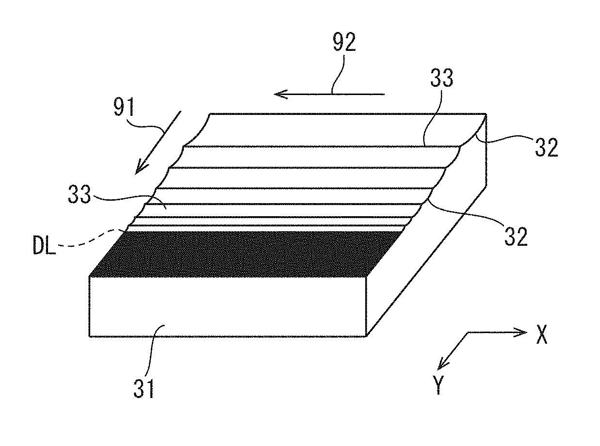
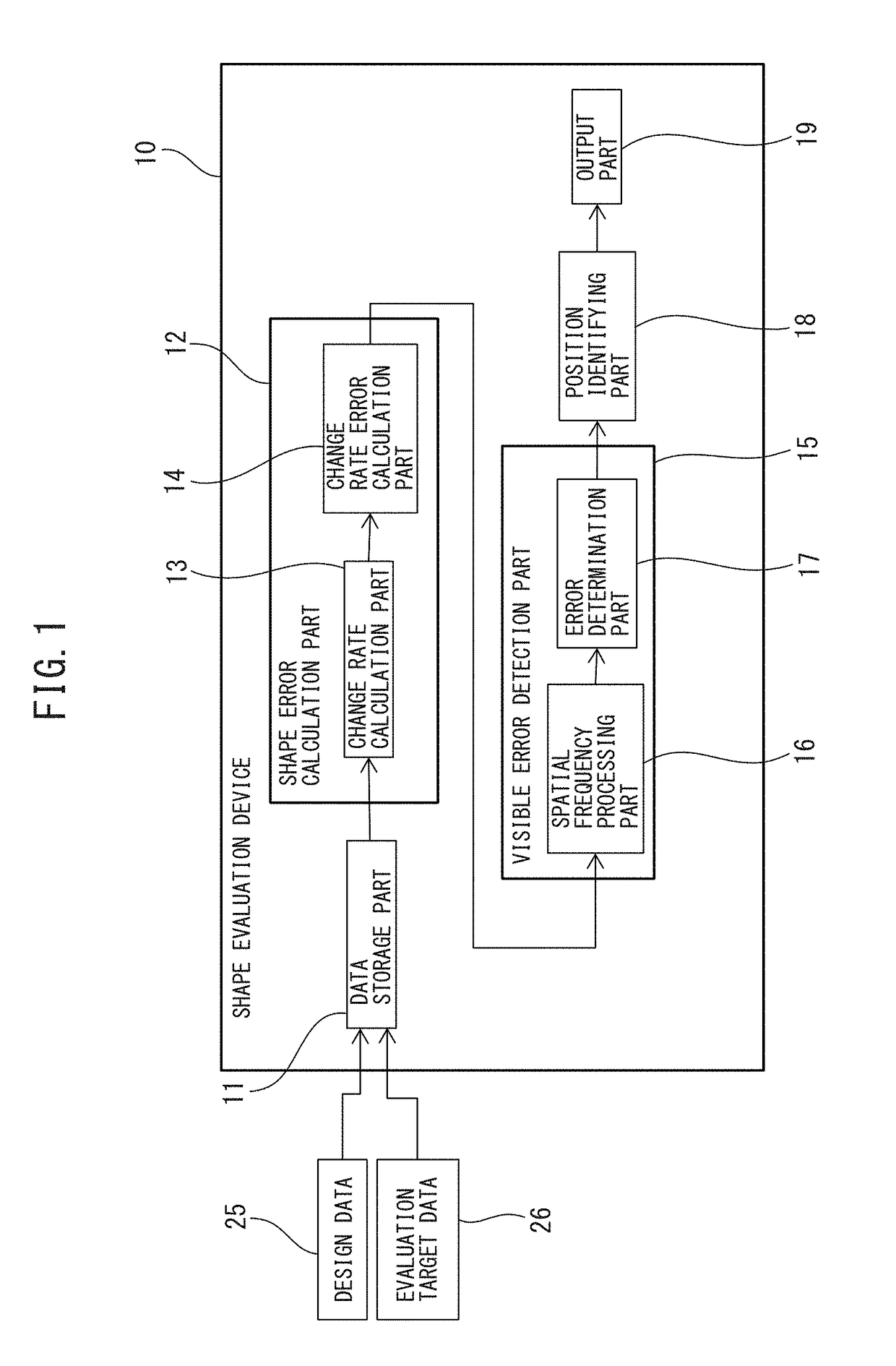
of the InventionA shape evaluation method and a shape evaluation device according to an embodiment will be explained with reference to FIG. 1 to FIG. 14. FIG. 1 shows a block diagram of a shape evaluation device according to the present embodiment. In the present embodiment, an object to be evaluated is referred to as a target object. The shape evaluation device compares the shape of a processed target object with the shape of a target object in design.

[0034]The shape evaluation device 10 is a device that evaluates the shape of the surface of the target object. Examples of target objects to be evaluated include industrial products such as molds, mechanical parts, automobile bodies, or articles which need design. The shape evaluation device 10 is constituted by, for example, an arithmetic processing device including a CPU (Central Processing Unit), a RAM (Random Access Memory), and ROM (Read Only Memory) and the like connected to each other via a bus.

[0035]The shape evaluation device...


PUM


Abstract

A shape evaluation method according to the present invention comprises: a shape error calculation step that calculates a shape error, which is an error between a designed shape and a shape to be evaluated; and a visible error detection step that detects visible shape errors on the basis of the shape error and predetermined visual characteristic data.

Description

CROSS-REFERENCE TO RELATED APPLICATIONS[0001]This application is a U.S. National Stage Application of International Patent Application No. PCT / JP2016 / 053074, filed on Feb. 2, 2016, which claims priority to Japanese Application No. 2015-021309, filed on Feb. 5, 2015, which are hereby incorporated by reference in the present disclosure in its entirety.FIELD OF THE INVENTION[0002]The present invention relates to a shape evaluation method and a shape evaluation device of a target object.BACKGROUND OF THE INVENTION[0003]The quality of the surface of the workpiece is evaluated in a workpiece machined by a machine tool or the like. The quality of the surface affects not only the aesthetic appearance of the surface as seen by a person but also the design as seen by a person. For example, when the quality of the surface is poor, lines and patterns may be visible in undesired areas. In particular, when the object to be evaluated is a mold, the shape of the surface of the mold is transferred t...

Claims


Application Information

Patent Timeline
Patent Type & Authority Applications(United States)
IPC IPC(8): G01B21/30
CPCG01B21/30G01B21/042G01B21/20G01N21/88G05B19/41875G06T7/0004G06T7/001G05B2219/32186G06T2207/30164Y02P90/02
Inventor SATO, RYUTASATO, YUKIODA, MITSUNARINAKAYAMA, NOBU
Owner MAKINO MILLING MASCH CO LTD
Why Eureka
Try Eureka