
Vertically stacked floors

a vertical and stacked technology, applied in the direction of dwelling buildings, construction, building construction, etc., can solve the problems of difficulty in including, within the building customized units, individual rooms with higher cathedral or loft ceilings, etc., and achieve the effect of increasing adaptability

Inactive Publication Date: 2017-12-21
BERGMAN GEORGE
View PDF1 Cites 4 Cited by
  • Summary
  • Abstract
  • Description
  • Claims
  • Application Information

AI Technical Summary

Benefits of technology

The invention provides a building structure consisting of vertically stacked units with cathedral ceilings that can be easily incorporated into the layout of a building without requiring additional reinforcement or design changes. The building structure has increased adaptability, allowing for the placement of specialized units at different locations in a building and providing the opportunity for mid- or bottom-storey placements. Additionally, the building structure allows for the formation of upgraded building modules with cathedral ceilings and secondary living areas for specific floor plan requirements, while also providing economical options for remaining portions of the building.

Problems solved by technology

The nature of vertically stacked building unit construction makes it difficult to include, within the building customized units, individual rooms with higher cathedral or loft ceilings or which otherwise have a differing vertical height from either vertically and / or horizontally adjacent units within the building, or for that matter separate living areas within the unit itself.
As a result of concerns of structurally weakening the building, there has been a reluctance to include within buildings, units having differing ceiling height configurations, for fear that this would necessitate additional structural reinforcement and architectural input.
Although some developers may include customized units, which have increased ceiling height, such units are typically restricted solely to the uppermost floor of a building, such as penthouse suites.

Method used


Image

  • Vertically stacked floors
  • Vertically stacked floors
  • Vertically stacked floors

Examples


second embodiment

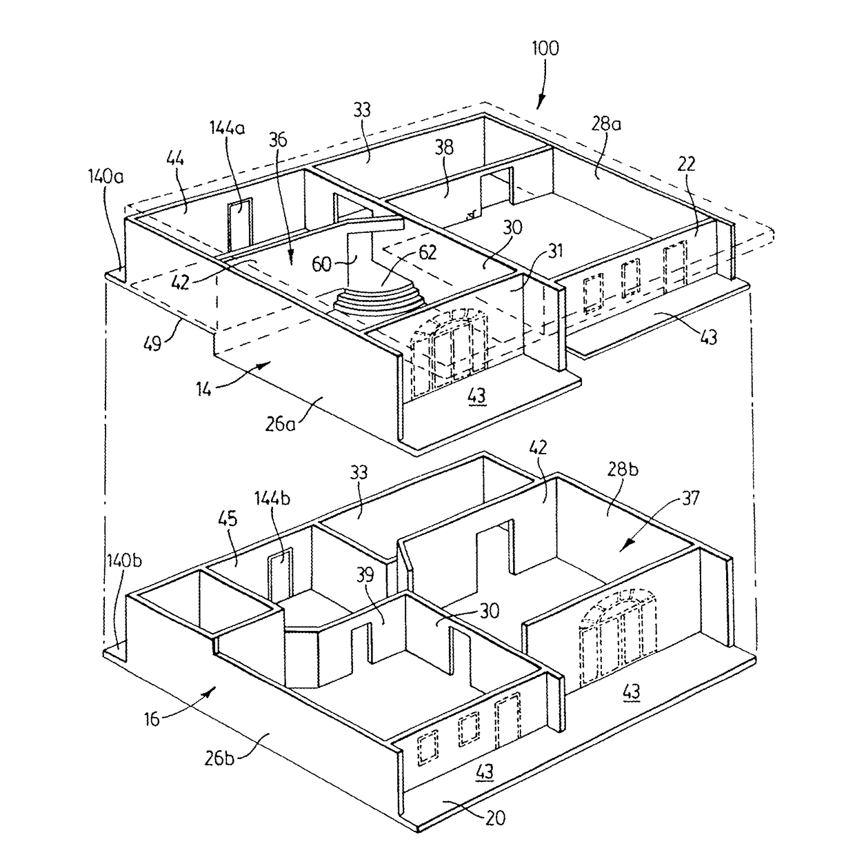
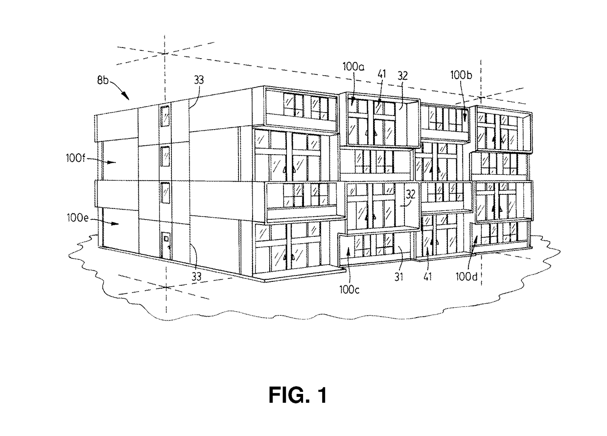
[0039]Reference may be made to FIGS. 1 to 7, which show a building 8B incorporating a number of building construction modules 100a-f in accordance with the invention, and wherein like reference numerals are used to identify like components. The modules 100a-f are of an identical or mirror construction and consist of upper and lower units 14, 16.

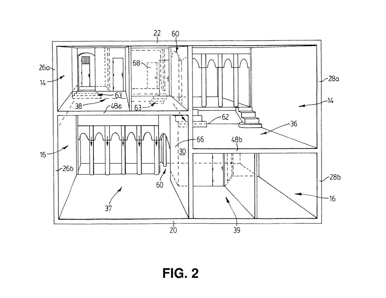
[0040]The module 100 of FIG. 1 has an overall height of approximately 2.5 conventional storeys with the forwardmost secondary living area 38, of the unit 14 consisting of a single one-storey unit positioned vertically directly above the primary living area 37 of the second other unit 16. The forwardmost secondary living area 39 of the lower unit 16 is positioned directly below the primary living area 36 of the upper unit 14. This configuration advantageously provides the primary living area 36, 37 of each unit 14, 16 with a cathedral height ceiling of 1.5 storeys.

[0041]FIG. 5 shows the concrete slab 49 placed approximately or exactly midway b...

first embodiment

[0045]By way of non-limiting example, reference may be had to FIG. 9 which illustrates schematically one possible alternate high-rise building 8 in which like reference numerals are used to identify like components. The building 8 of FIG. 9 is shown as incorporating a number of the building modules 10 in accordance with the invention, shown by reference numeral 120 as occupying the uppermost six storeys of the building 8, a number of modules 100, shown by reference numeral 122 as occupying the middle five storeys of the building 8, and a lowermost zone 124 of single conventional one storey residential units 126.

[0046]Although the detailed description describes the present construction modules as being used in concrete based structures, any brick or wood structure having a design appropriate for different modules may be used in a townhome or detached home construction. By way of non-limiting example, FIG. 10 shows one such townhome construction in which like reference numerals are us...


PUM


Abstract

A building structure suitable as a pair of floors each contains at least one pair of stacked units, which may be incorporated into a variety of multi-storey commercial or residential buildings. The structure includes two or more vertically stacked units which each define a respective self-contained space. As a floor module, the building structure extends downward from a planar ceiling surface, which forms the ceiling of an uppermost unit to a planar lower floor surface of the second lower other unit. Together, the pair of stacked units has an overall height equal to two and one-half to three full storeys, and a height selected between twenty-three and thirty-six feet, depending upon the respective building structure (7.5-12 feet). An interior dividing bearing wall is positioned within each of the units between the load-bearing sidewalls, and which divide each unit into primary and secondary living areas or spaces.

Description

RELATED APPLICATION[0001]This application is a continuation of U.S. patent application Ser. No. 10 / 372,948 filed on Feb. 26, 2003, which claims priority to a continuation-in-part of U.S. patent application Ser. No. 10 / 046,898, filed on Jan. 17, 2002, the contents of all of which are incorporated herein by reference.SCOPE OF THE INVENTION[0002]The present invention relates to a building, condominium or townhouse structure, which includes at least two floors, containing one or more vertically stacked building units. Specifically, the present invention relates to a stacked building unit construction consisting of at least two self-contained units. Most preferably, the units are part of a typical floor plan size of particular architectural project, each unit having areas with both conventional ceiling height and areas with higher cathedral or loft-type ceilings. The units are further characterized by a planar parallel horizontal uppermost ceiling and lowermost floor surface arrangement....

Claims


Application Information

Patent Timeline
Patent Type & Authority Applications(United States)
IPC IPC(8): E04B1/348E04H1/04
CPCE04H1/04E04B1/34823
Inventor BERGMAN, GEORGE
Owner BERGMAN GEORGE
Learn More