
Stereo imaging system

Active Publication Date: 2017-12-07
BAKER HUGHES INC
View PDF2 Cites 0 Cited by
  • Summary
  • Abstract
  • Description
  • Claims
  • Application Information

AI Technical Summary

Benefits of technology

The patent describes a special optical system that creates better 3D images. It uses a roof prism, dual apertures, and separated ray paths to improve the viewing experience.

Problems solved by technology

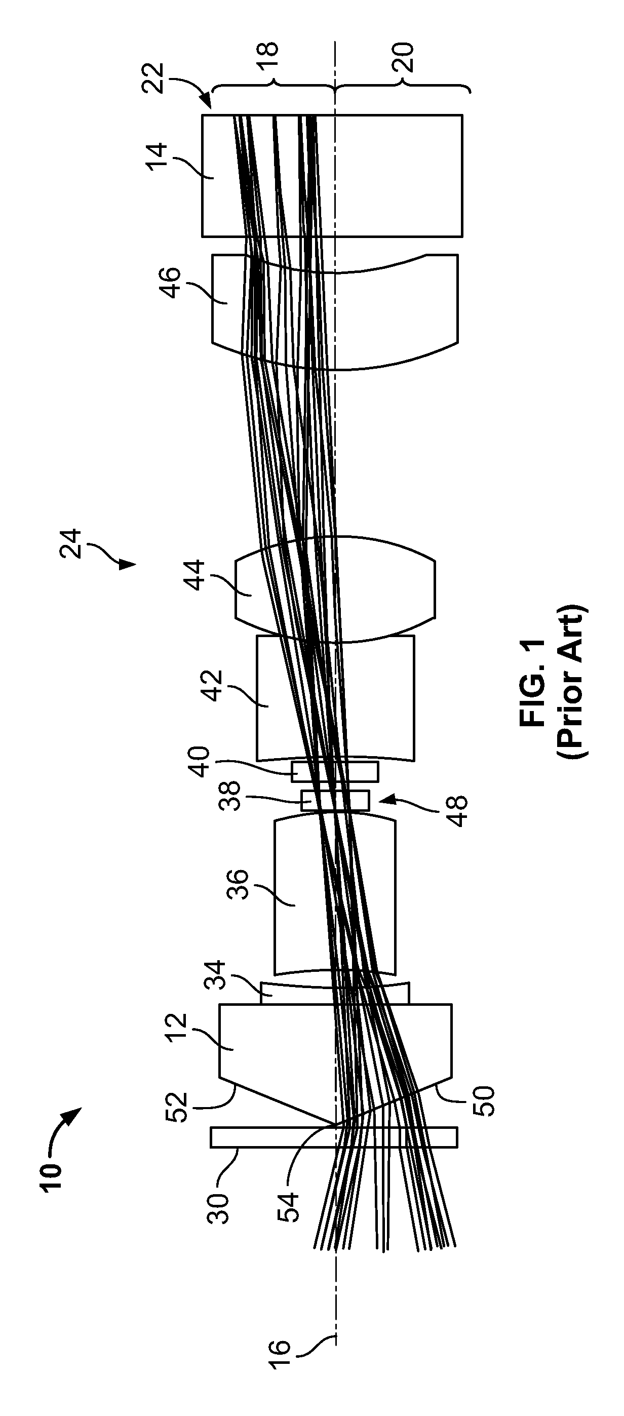
Current stereo imaging systems that contain a roof prism (bi-prism) may have imaging aberration issues.
Some of these rays will cause image degradation at the image plane.
However, the existing optical system 10 is of a single aperture optics design and thus can have at least some issues and / or challenges.
A first issue, imaging aberration, can include color separation, astigmatism and / or field curvatures that can be difficult to correct due to the roof prism nature.
A second issue can be that the stereo image separation might be limited by a prism angle and a small envelope size of a borescope or endoscope camera.
A third issue can be that the stereo imaging is very sensitive to optical component position deviations from perfection (i.e., tolerances).
Examples of image degradation include undesirable color separation, undesirable contrast, undesirable contrast, image size distortion, image shape distortion, vignetting, etc.

Method used


Image

  • Stereo imaging system
  • Stereo imaging system
  • Stereo imaging system

Examples


Embodiment Construction

[0021]Example embodiments that incorporate one or more aspects of the disclosed subject matter are described and illustrated in the drawings. These illustrated examples are not intended to be a limitation on the disclosed subject matter. For example, one or more aspects of the disclosed subject matter can be utilized in other embodiments and even other types of devices. Moreover, certain terminology is used herein for convenience only and is not to be taken as a limitation on the disclosed subject matter. Still further, in the drawings, the same reference numerals are employed for designating the same elements.

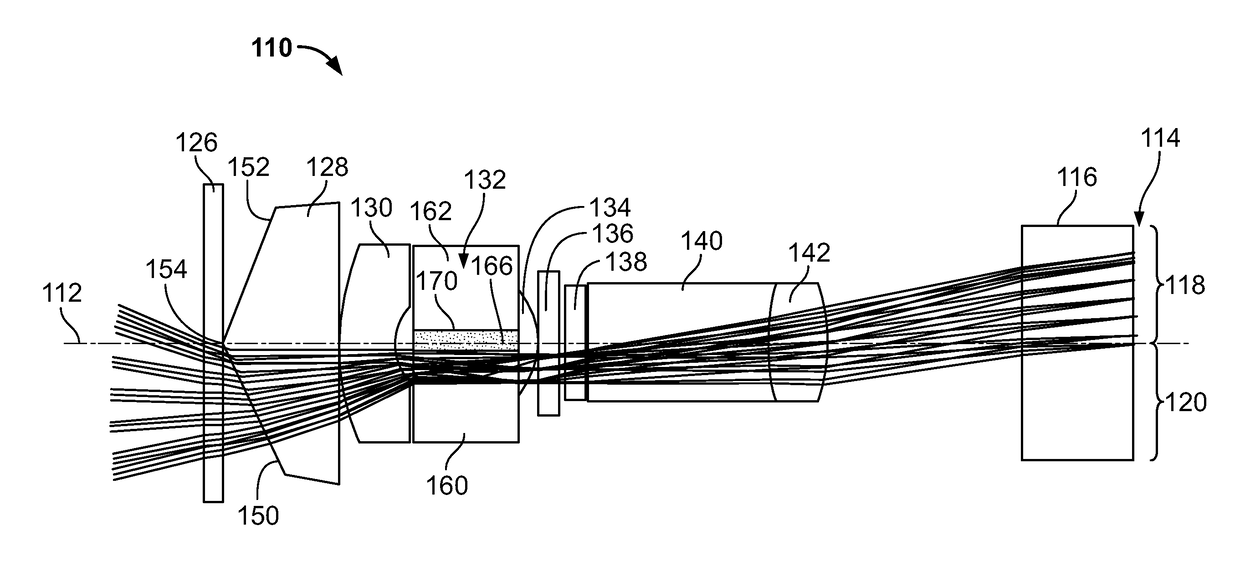
[0022]The subject matter relates to a stereoscopic optical system, with a roof prism, dual apertures within a single lens system and separated ray paths, which provides for improved stereo images. Better images can be provided by selectively preventing some optical rays from proceeding to the image areas.

[0023]Current stereo imaging systems that contain a roof prism (bi-prism)...


PUM


Abstract

A stereoscopic optical system that includes an image member that is located at a position along a center optical axis and that has a first stereoscopic image area on a first side of the optical axis for receipt of a first stereoscopic image thereon and a second, separate stereoscopic image area on a second, separate side of the optical axis for receipt of a second, separate stereoscopic image thereon. The system includes an optical arrangement extending along the center optical axis and includes a roof prism with first and second roof segments. The arrangement is configured to transmit image-forming rays passing through the first roof segment to the first stereoscopic image area along a first optical path through the arrangement and is configured to transmit image-forming rays passing through the second roof segment to the second stereoscopic image area along a second, different optical path through the arrangement.

Description

RELATED APPLICATION[0001]The present application is a non-provisional application and claims benefit of priority from U.S. Provisional Patent Application No. 62 / 343,988, filed Jun. 1, 2016, which is incorporated herein by reference.FIELD OF THE SUBJECT MATTER[0002]This subject matter relates generally to the field of borescopes and endoscopes, and more particularly a borescope / endoscope which can provide a 3D image from a single camera and lens system.BACKGROUND[0003]Current stereo imaging systems that contain a roof prism (bi-prism) may have imaging aberration issues. With reference to FIG. 1, note that a great amount of optical rays can proceed through each roof segment of a roof prism (only the rays for one of the two roof segments is shown to avoid drawing clutter). Some of these rays will cause image degradation at the image plane.[0004]FIG. 1 is a schematic representation of a stereoscopic optical system 10. It is to be noted at the outset that the existing optical system 10 c...

Claims


Application Information

Patent Timeline
IPC IPC(8): G02B23/24H04N13/00H04N13/02
CPCG02B23/2415G02B23/2484H04N13/0018H04N13/0203H04N2213/001H04N13/218H04N13/204
Inventor YANG, DONGMIN
Owner BAKER HUGHES INC
Learn More