
In-vehicle battery module

a battery module and vehicle battery technology, applied in the direction of batteries, cell components, sustainable manufacturing/processing, etc., can solve the problems of poor inability to ensure the electrical connection, and insufficient consideration of the structure for maintaining the performance of the battery module, so as to improve the reliability of the battery module and reduce the number of components

Active Publication Date: 2017-11-30
TOYOTA JIDOSHA KK
View PDF11 Cites 17 Cited by
  • Summary
  • Abstract
  • Description
  • Claims
  • Application Information

AI Technical Summary

Benefits of technology

The patent provides an in-vehicle battery module that is designed to be more reliable. The module is able to maintain its performance even when one of its components (adhesive) is damaged. This means that the battery module is more durable and less prone to failure.

Problems solved by technology

However, in the conventional battery module, there is no sufficient consideration about a structure for maintaining the performance of the battery module even when the members holding the cylindrical battery cells are partially damaged or degraded.
For example, in the battery module of JP 2010-113999 A, while the cylindrical battery cells are held between the pair of side plates, if either one of the side plates is damaged or bent, the cylindrical battery cells move in the axial direction, so that it is not possible to ensure the electrical connection.
In other words, in the conventional battery module, there is a problem that the electrical performance is impaired even only with damage to one component, resulting in poor reliability as a battery module.
In particular, such a problem tends to arise in an in-vehicle battery module that is subjected to various vibrations during travel of a vehicle.

Method used


Image

  • In-vehicle battery module
  • In-vehicle battery module
  • In-vehicle battery module

Examples


Embodiment Construction

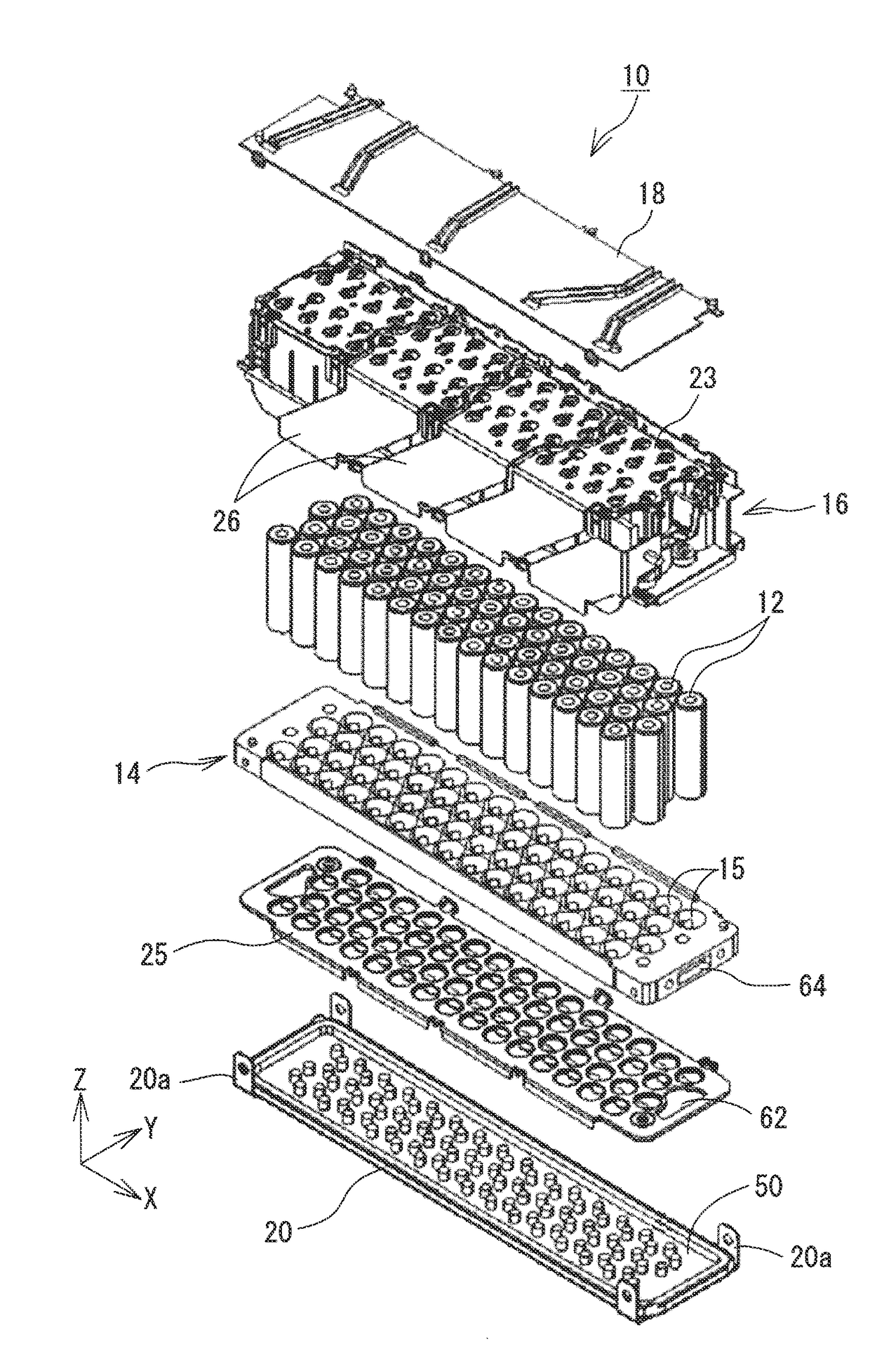
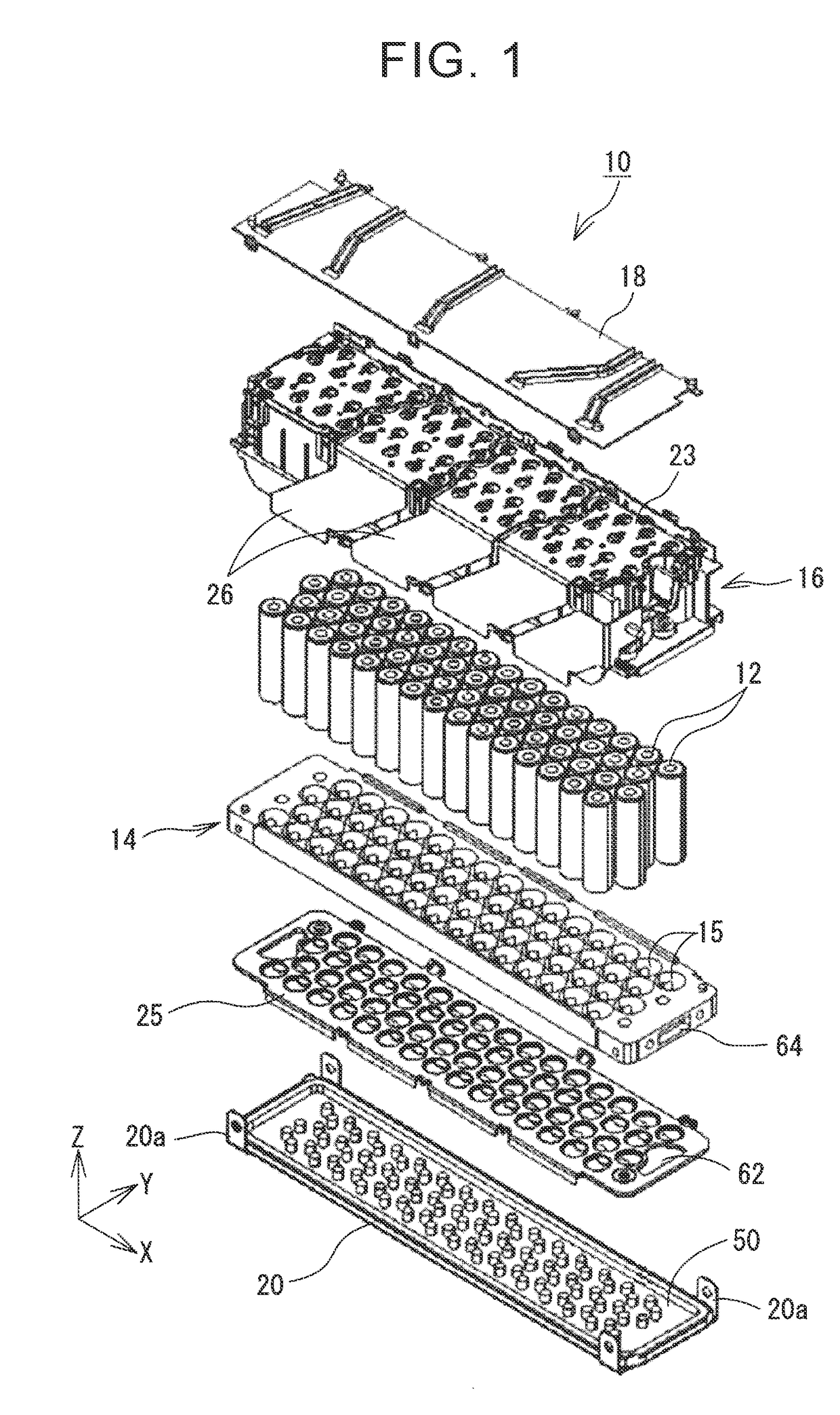
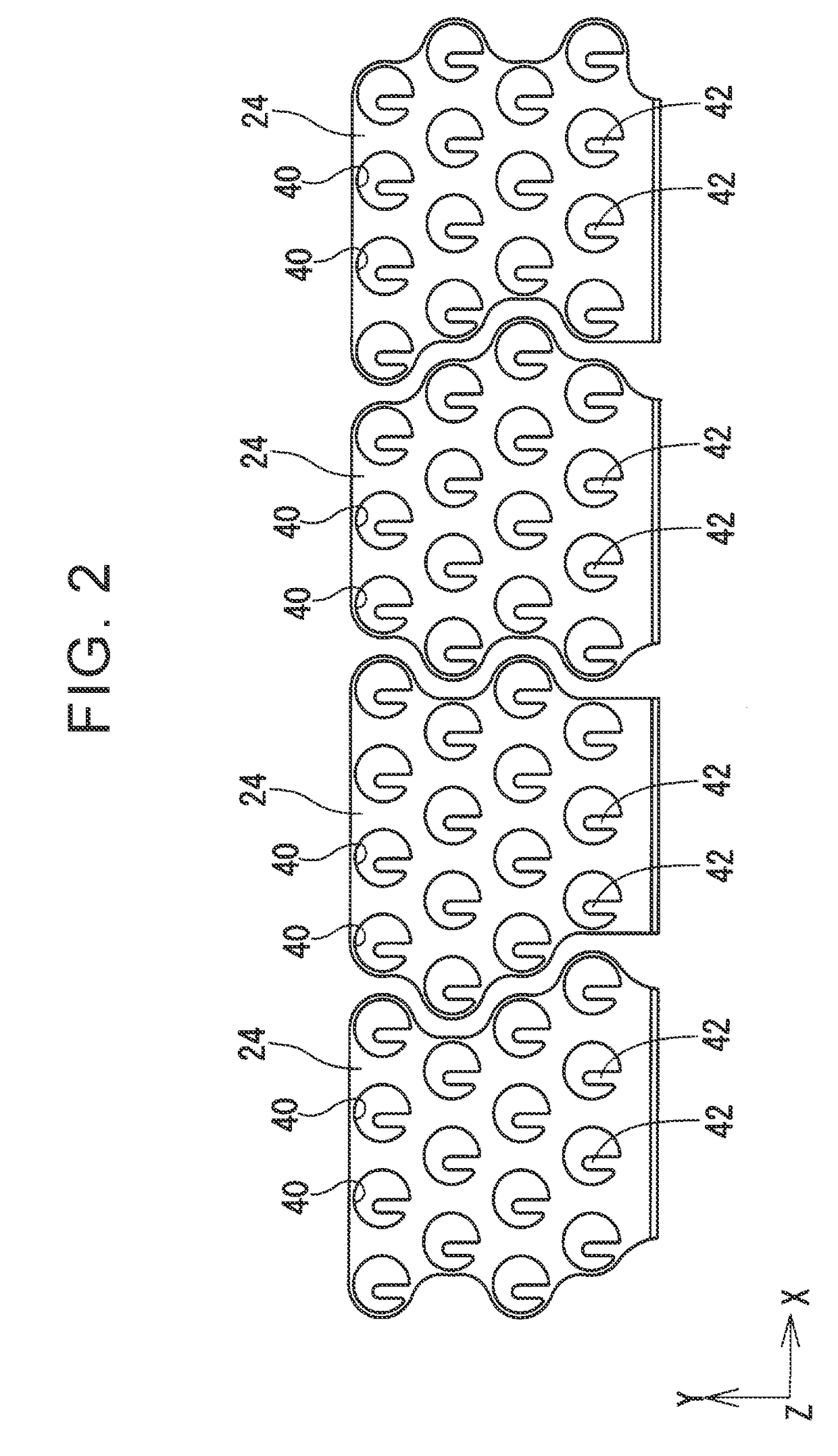
[0026]Hereinbelow, a battery module 10 according to an embodiment of the disclosure will be described with reference to the drawings. FIG. 1 is an exploded perspective view of the battery module 10 according to the embodiment of the disclosure. FIG. 2 is a plan view of conductive plates 24 of a negative-electrode bus bar 25, FIG. 3 is a perspective view of a vent cover 20 that is integrated with a support member 50, and FIG. 4 is a sectional view of the battery module 10 in the YZ plane. In the following description, a longitudinal direction of the battery module 10 will be referred to as an “X direction”, an axial direction of a battery cell 12 as a “Z direction”, and a direction perpendicular to the X direction and the Z direction as a “Y direction”.

[0027]The battery module 10 includes a plurality of cylindrical battery cells 12. The battery cell 12 is a chargeable and dischargeable secondary battery cell and may be, for example, a nickel-hydrogen battery cell or a lithium-ion bat...


PUM


Abstract

An in-vehicle battery module includes a plurality of cylindrical battery cells, a battery cell holder, a protective case, a vent cover provided such that the battery cell holder is positioned between the protective case and the vent cover, the vent cover and the battery cell holder disposed such that a vent space in which gas discharged from an end face on a second-electrode side of the cylindrical battery cell flows is provided between the vent cover and the battery cell holder, at least one first-electrode bus bar, at least one second-electrode bus bar provided in the vent space, and a support member disposed partially in the vent space and the support member being configured to support the second-electrode bus bar from the vent cover side.

Description

INCORPORATION BY REFERENCE[0001]The disclosure of Japanese Patent Application No. 2016-103344 filed on May 24, 2016 including the specification, drawings and abstract is incorporated herein by reference in its entirety.BACKGROUND1. Technical Field[0002]The disclosure relates to an in-vehicle battery module that includes a plurality of cylindrical battery cells and is installed in a vehicle.2. Description of Related Art[0003]Conventionally, there is known a battery module that includes a plurality of cylindrical battery cells and is installed in a vehicle. For example, Japanese Patent Application Publication No. 2010-113999 (JP 2010-113999 A) discloses a battery module including a plurality of cylindrical battery cells. In JP 2010-113999 A, a pair of side plates are disposed on both axial sides of the cylindrical battery cells and hold the cylindrical battery cells therebetween. Bus bars electrically connecting the cylindrical battery cells are embedded in the side plates. On the sid...

Claims


Application Information

Patent Timeline
IPC IPC(8): H01M2/10H01M2/12H01M2/20H01M2/02H01M10/04H01M10/52H01M50/213H01M50/227H01M50/249H01M50/507H01M50/51H01M50/512H01M50/522
CPCH01M2/105H01M2/1083H01M2/1205H01M2/1077H01M2/1094H01M10/0486H01M2/025H01M2220/20H01M10/52H01M10/0422H01M2/206H01M50/30H01M50/512H01M50/507B60L50/64H01M50/51H01M50/522H01M50/227H01M50/213H01M50/249Y02E60/10H01M50/308H01M50/24H01M50/3425Y02P70/50Y02T10/70H01M10/625H01M10/643H01M50/138
Inventor MORIOKA, SATOSHI
Owner TOYOTA JIDOSHA KK
Learn More