Bracket-equipped vibration-damping device

Active Publication Date: 2017-11-30
TOKAI RUBBER IND LTD
View PDF0 Cites 12 Cited by
  • Summary
  • Abstract
  • Description
  • Claims
  • Application Information

AI Technical Summary

Benefits of technology

The present invention provides a bracket-equipped vibration-damping device with a simple structure that is easy to manufacture. The device can stably retain the bracket in an appropriate mounted state to the main body. This results in a more effective and efficient device with improved performance.

Problems solved by technology

However, for the retainment structure using the snap-fitting shown in US 2010 / 0264570, upon assembly of the vibration-damping element and the support body, at least one of the rib including the snap-fitting lug and the slider including the notch must undergo elastic deformation, so that the structure suffers from damages made during the deformation and the like.
Especially if the at least one of the rib and the slider is formed of a synthetic resin for weight reduction and formability improvement, the vibration-damping device readily suffers from damages of the vibration-damping element and the support body caused by the elastic deformation in mounting the support body.
This may lead to secular deterioration, which might give rise to separation of the vibration-damping element and the support body as well.
On the other hand, if you try to form the snap-fitting lug and the notch that are elastically deformable with respect to the rib and the slider that are formed of a metal, it becomes difficult to manufacture the rib and the slider by molding.
Therefore, the support body, which includes the slider, being formed of such material like a synthetic resin that the dimension may change by secular deterioration could suffer from noise caused by rattling due to a gap between the vibration-damping element and the support body.

Method used


Image

  • Bracket-equipped vibration-damping device
  • Bracket-equipped vibration-damping device
  • Bracket-equipped vibration-damping device

Examples


first embodiment

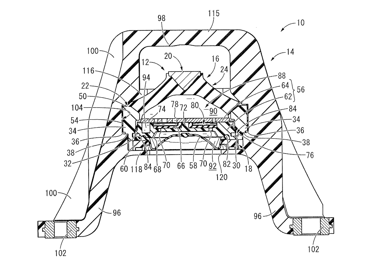
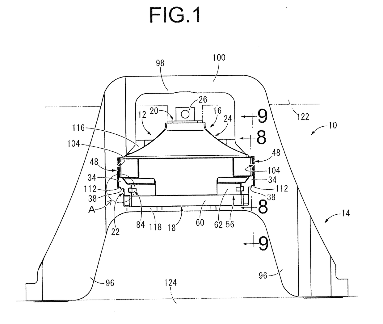
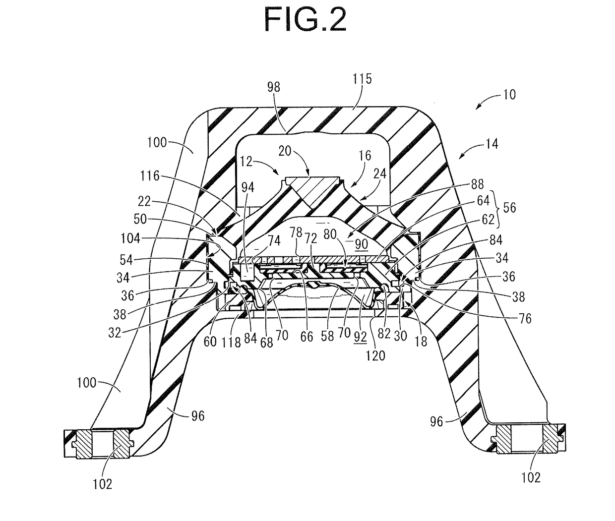
[0063]FIGS. 1 and 2 show an automotive engine mount 10 as a bracket-equipped vibration-damping device constructed according to the present invention. The engine mount 10 has a structure wherein a mount main body 12 as a vibration-damping device main body is attached to a bracket 14 such that it is inserted in the lateral direction into the bracket 14. In the explanation hereinafter, as a general rule, the up-down direction is the up-down direction in FIG. 1, which is the direction of the mount central axis, the front-back direction is the direction orthogonal to the paper face of FIG. 1, and the left-right direction is the left-right direction in FIG. 1, respectively.

[0064]More specifically, the mount main body 12, as shown in FIGS. 3 and 4, comprises an integrally vulcanization molded component 16 and a fluid-filled assembly 18, which are combined. The integrally vulcanization molded component 16 has a structure wherein a first mounting member 20 and a second mounting member 22 are...

second embodiment

[0117]Next, FIGS. 11 and 12 show an automotive engine mount 210 as the bracket-equipped vibration-damping device constructed according to the present invention. The engine mount 210 has a structure wherein a mount main body 212 as a vibration-damping device main body is attached to a bracket 214 such that it is inserted in the lateral direction into the bracket 214. In the explanation hereinafter, as a general rule, the up-down direction is the up-down direction in FIG. 11, which is the direction of the mount central axis, the front-back direction is the direction orthogonal to the paper face of FIG. 11, and the left-right direction is the left-right direction in FIG. 11, respectively.

[0118]More specifically, the mount main body 212, as shown in FIGS. 13 and 14, comprises an integrally vulcanization molded component 216 and a fluid-filled assembly 218, which are combined. The integrally vulcanization molded component 216 has a structure wherein a first mounting member 220 and a seco...


PUM


Abstract

A bracket-equipped vibration-damping device including: a vibration-damping device main body including vertically-separated, elastically-connected first and second mounting members; a bracket receiving the device main body inserted laterally thereinto; a connection-insert section provided for the second mounting member; a connection groove provided for the bracket extending in an insertion direction of the device main body; at least one up-down urging rubber fixed on an outer surface of the connection-insert section on an upper-lower first side; and a lock protrusion formed on an inner surface of the connection groove on an upper-lower second side, with a smaller protrusion dimension than an up-down thickness of the up-down urging rubber such that the connection-insert section is laterally inserted into the connection groove beyond the lock protrusion before being urged to the second side by the up-down urging rubber to be positioned to the connection groove.

Description

INCORPORATED BY REFERENCE[0001]The disclosures of Japanese Patent Application Nos. 2016-108312 filed on May 31, 2016 and 2016-116485 filed on Jun. 10, 2016, each including the specification, drawings and abstract is incorporated herein by reference in its entirety.BACKGROUND OF THE INVENTION1. Field of the Invention[0002]The present invention relates to a bracket-equipped vibration-damping device used for an automotive engine mount etc.2. Description of the Related Art[0003]From the past, a vibration-damping device has been known as a kind of vibration-damping support body or vibration-damping connecting body that is interposed between members constituting a vibration-damping system to provide mutual vibration-damping linkage between the constituent members of the vibration-damping system. For example, the vibration-damping device is applied to an automotive engine mount or the like. This vibration-damping device has a vibration-damping element wherein a second strength member and a...

Claims


Application Information

Patent Timeline
IPC IPC(8): B60K5/12F16F3/087F16F15/08F16F1/36F16F13/08
CPCB60K5/1208F16F1/3605F16F13/085F16F15/08F16F3/0873F16F7/00F16F13/108F16F13/103F16F1/3849F16F2226/041
Inventor OKI, KENJIOKUMURA, KEIKANAYA, TOMOHIRO
Owner TOKAI RUBBER IND LTD
Why Eureka
Try Eureka