
Padmount transformer with energy storage apparatus

a transformer and energy storage technology, applied in the field of transformers, can solve the problems of insufficient energy produced by one, unsatisfactory solutions, and variable and unpredictable renewable energy production, and achieve the effect of increasing the level of renewable energy sources, efficient and cost-effectiv

Active Publication Date: 2017-11-23
HITACHI ENERGY SWITZERLAND AG
View PDF10 Cites 1 Cited by
  • Summary
  • Abstract
  • Description
  • Claims
  • Application Information

AI Technical Summary

Benefits of technology

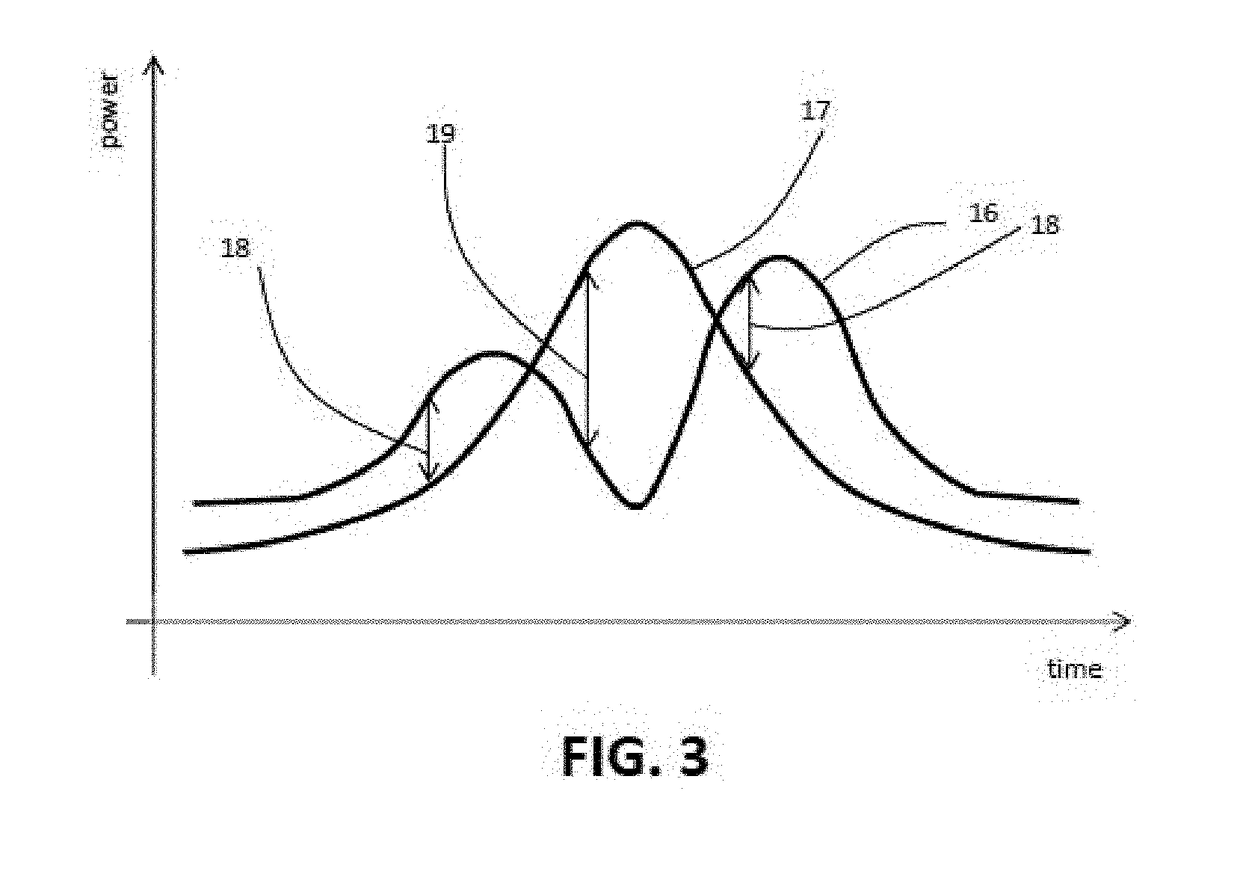
The padmount transformer in this patent helps absorb energy from renewable sources during peak production, reduces power reversal in the distribution network, and stores excess energy close to the generation site for later use. It also regulates voltage to allow for greater integration of renewable power without making significant changes to the distribution network. Additionally, it provides reliable electrical energy to sensitive customers and loads, ensuring continuous energy flow during power outages.

Problems solved by technology

The renewable energy production tends to be variable and unpredictable.
From an energetic point of view, this is not convenient because it causes power losses in the power distribution network since the energy has to be sent kilometres away to be used and the voltage at transformers side might increase and become too high to be acceptable for the electrical equipment forcing the electrical distributor in making important investments to manage the problem.
This solution, however, is not fully satisfactory because it does not solve the problem of the shift between the peak of production and the peak of demand.
Moreover, the energy produced by one are may be not sufficient for the area itself and the additional areas.
This solution however implies high investments in the network and does not solve the problem of power losses in the network since water basins can be extremely far away from the location where the energy is first produced.
This solution however has the problem of a low effectiveness, leaves the problem to the discretion of the single user and is not satisfactory on a larger scale, for example in a city district where some users have renewable power sources with batteries and some other users have power sources with no batteries.
However, this solution is expensive and requires a regular maintenance of UPS that a normal user might be not able to provide.

Method used


Image

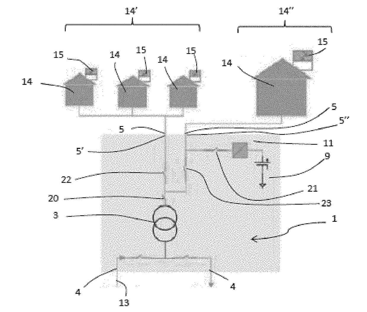
  • Padmount transformer with energy storage apparatus
  • Padmount transformer with energy storage apparatus
  • Padmount transformer with energy storage apparatus

Examples


Embodiment Construction

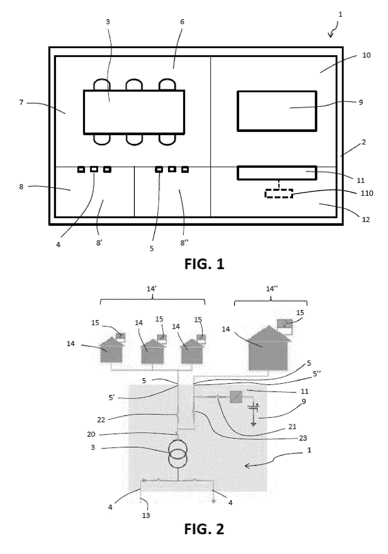
[0027]In the following description, same alphanumeric references are used for analogous exemplary elements when they are depicted in different drawings.

[0028]With reference to the attached Figures, a padmount transformer according to the present disclosure is indicated with reference number 1. The padmount transformer 1 can be used for example for supplying low voltage energy to a city district, to a commercial building for its own supply, to small industries, et cetera. The padmount transformer 1 is mainly intended to be installed outdoor.

[0029]The padmount transformer comprises a cabinet 2 configured to house a single-phase or three-phase electrical distribution transformer 3 to be mounted on a ground level platform or pad. Such a distribution transformer 3 is used to step down voltage from a high / medium voltage terminal of an underground electrical distribution system to a low voltage terminal thereof, and includes a core / coil assembly, and electrical connectors, in particular hi...


PUM

PropertyMeasurementUnit
voltageaaaaaaaaaa
poweraaaaaaaaaa
concentrationaaaaaaaaaa

Abstract

The present disclosure is directed to a padmount transformer. The padmount transformer includes an electrical distribution transformer housed in a cabinet that can be mounted on a ground level platform or pad. High / medium voltage connectors of the electrical distribution transformer can connect to high / medium voltage terminals of a power supply network. Low voltage connectors of the electrical distribution transformer are configured to connect to low voltage terminals of one or more loads coupled to respective renewable energy sources. The high / medium voltage connectors and the low voltage connectors are housed in the cabinet. An energy storage apparatus is housed in the cabinet and is connected with the low voltage connectors for supplying power to the loads. Power can be supplied to the energy storage apparatus by the renewable energy sources. An inverter is operable for commanding the power supply direction at the energy storage apparatus and a control unit is configured to control the inverter.

Description

BACKGROUNDTechnical Field[0001]The present disclosure relates to a transformer, in particular to a padmount transformer, i.e. a ground mounted electric power distribution transformer housed in a locked cabinet to be mounted on a ground level platform or a concrete pad. The transformer according to the present disclosure is provided with an energy storage apparatus and is to be integrated in a system where at least some customers / loads supplied by the transformer are provided with renewable energy sources. The transformer according to the present disclosure is particularly suitable to handle the situation in which some customers / loads are subjected to black-outs and require technical solutions to manage the black-out conditions.Description of the Related Art[0002]Padmount transformers are used with underground electric power distribution lines at service drops and convert the power distribution network high or medium voltage to a low voltage supplied to loads, such as buildings, indu...

Claims


Application Information

Patent Timeline
Patent Type & Authority Applications(United States)
IPC IPC(8): H02J3/38H01F27/06H01F27/29H02M7/44H01F27/02
CPCH02J3/383H02J3/386H02J3/387H01F27/06H01F27/29H01F27/02H02M7/44Y02E70/30H02J3/32H02J2300/28H02J2300/24H02J3/381Y02E10/56Y02E10/76
Inventor CEREDA, CARLOBAYOUMI, DEIA
Owner HITACHI ENERGY SWITZERLAND AG
Learn More