
Direct current electric arc furnace for metallurgical plant

Inactive Publication Date: 2017-11-16
DANIELI & C OFF MEC SPA
View PDF6 Cites 0 Cited by
  • Summary
  • Abstract
  • Description
  • Claims
  • Application Information

AI Technical Summary

Benefits of technology

This patent aims to create a bottom electrode that has several benefits. Firstly, it can help to maintain a lower temperature compared to existing electrodes, which makes it safer. Secondly, it can help to decrease the thermal and chemical stress placed on the furnace bottom, leading to better efficiency. Lastly, the electrodes tend to have a uniform current passage and lower intensity, reducing wear and tear.

Problems solved by technology

The anodes in these furnaces are one of the most delicate components as they are crossed by currents having very high intensity and are subject to significant thermal stresses and electromagnetic forces.
A further problem to be considered in an electric furnace, and in particular in a DC direct current furnace, concerns the cooling of the furnace bottom.
If the furnace bottom constantly maintains very high temperatures, this negatively affects the duration of the base and of the insulating materials which prevent part of the electric current circulating in the anodes from reaching the framework of the furnace and damaging it.
The wear of the covering decreases the safety of the work environment and there is a need to frequently change the hearth, an operation which stops the plant.
In such a situation, if the fusion front inside the anode should continue up to completely perforating the anode base, contact would occur of the liquid metal with the water or other cooling liquid used to cool down the anode base, thus causing a highly dangerous explosive reaction.

Method used


Image

  • Direct current electric arc furnace for metallurgical plant
  • Direct current electric arc furnace for metallurgical plant
  • Direct current electric arc furnace for metallurgical plant

Examples


Embodiment Construction

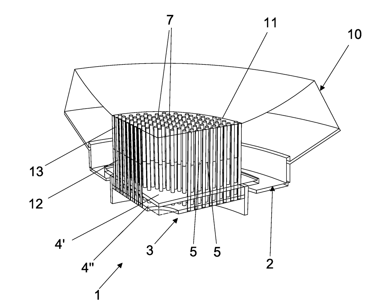
[0046]With reference to FIG. 1, a direct current electric arc furnace, only partly depicted, is indicated as a whole with numeral 1. Furnace 1 is described only partly with particular reference to the elements that distinguish it from known furnaces. The parts of the furnace not described in detail are intended in themselves known and conventional.

[0047]Furnace 1 comprises a bottom 2, which includes one or more bottom electrodes 3, or lower electrodes, typically supplied electrically by the positive polarity, incorporated in a base sole 10, which acts as a matrix, made of refractory material, preferably high melting point ceramic. FIG. 1 shows a single bottom electrode 3. Bottom 2 is part of the base sole 10 of furnace 1. The base sole 10 further comprises an upper surface 11 susceptible to being in contact with the metal mass or metal bath contained in furnace 1.

[0048]With reference to FIGS. 1 to 3, the bottom electrode 3 comprises a base or support flange 4. Flange 4 is provided w...


PUM


Abstract

A direct current electric arc furnace (1) for metallurgical plant comprises an electrode (3) having a base (4) and a plurality of metal bars (5) fixed to the base (4); each of said metal bars (5) comprises at least a first portion (12) and at least a second portion (13) which is axially adjacent to said first portion (12), said first portion (12) being restrained to said base (4) and having greater thermal conductivity with respect to said second portion (13).

Description

CROSS REFERENCE TO RELATED APPLICATIONS[0001]The present application claims priority to PCT International Application No. PCT / IB2015 / 059144 filed on Nov. 26, 2015, which application claims priority to Italian Patent Application No. MI2014A002045 filed Nov. 17, 2014, the entirety of the disclosures of which are expressly incorporated herein by reference.STATEMENT RE: FEDERALLY SPONSORED RESEARCH / DEVELOPMENT[0002]Not Applicable.FIELD OF THE INVENTION[0003]The present invention relates to a direct current electric arc furnace usable in a metallurgical plant.BACKGROUND ART[0004]Direct current electric furnaces (also known with the acronym DC EAFs, Direct Current Electric Arc Furnaces) are used mainly in the steel industry for melting and refining iron-based metal alloys.[0005]In these furnaces, the electric arc is discharged between at least one graphite electrode arranged above (cathode) and at least one bottom electrode (anode) arranged below in the base sole of the furnace. The passi...

Claims


Application Information

Patent Timeline
IPC IPC(8): G01L1/14B81B3/00G01D5/24
CPCG01L1/14B81B3/0027B81B3/0072G01D5/2405H05B7/06
Inventor MORSUT, STEFANOFORNO, FERDINANDOCODUTTI, ANDREAPICIOTTO, MAURIZIO
Owner DANIELI & C OFF MEC SPA
Learn More